Bal-tec™ Home Using the Probe Characterizing or Calibration Sphere
Using the Probe Characterizing or Calibration Sphere

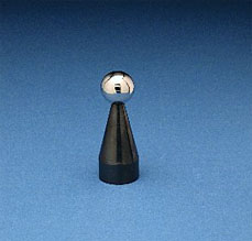
This Probe Characterizing technique uses computer software and an extremely high quality spherical artifact of a well known diameter to calibrate the radius of the contact tip. It will characterize geometry errors of the measuring probe (probe lobbing), it will compensate for bending of the probe stem and a broad range of other elastic deflections or bending moments throughout the machine. The sphere is very rigidly fixed to the C.M.M. table for this test. In effect, the C.M.M.'s computer is told that it is measuring a perfect sphere of a specific diameter and that any departure from this ideal form should be corrected in all future measurements. Some C.M.M. software is written around a specific master sphere diameter while other software is open to selection by the user.
The most widely used sphere diameter is one inch (25.4mm) but 3/4 inch (19.05mm) is also widely used. In our experience down to about 10mm (.3937 inch) diameter, the smaller the master sphere used, the more accurately probe lobbing will be compensated for. This correction ends up being a simple adjustment in the apparent radius of the contact tip of the measuring probe (see Fig. #30.).
Repeatability Test
This same spherical artifact makes an excellent Coordinate Measuring Machine repeatability test device. Its position on the table and its diameter are simply measured a considerable number of times (usually ten to twelve), and the results are compared. Each measurement consists of a small number of well distributed hits. Any variations in the measurements reflect a lack of machine repeatability. Valuable information about specific machine performance can be learned by looking at the end positions of individual axii. Note that this test must be performed as quickly as possible to avoid the influence of temperature drift. (For additional information see page 22 ).
