Bal-tec™ Home Kinematic Stability
Kinematic Stability — A Mechanically Stable Kinematic Platform
Wobbly, would be a good way to describe the famous three legged milking stool. (See Figure #1.)
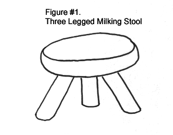
Three points will always define a plane, but that does not make it a mechanically stable coupling. When is the last time that you saw a three legged table or chair?
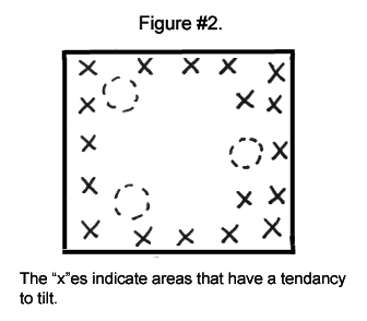
A three point kinematic mount is no more mechanically stable than the three legged milking stool. They will wobble if off center loads are applied. The most common example of this need is when the payload is concentrated off center at the edge or in a corner that doesn’t have a matching kinematic couple. (See Figure #2.)
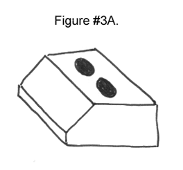
When the mechanical stability, of a kinematic system, is a major concern, particularly when off center loads are applied, a “Split Kinematic Coupling” will be the best approach to use. The Split Kinematic Vee Block half of the couple, is formed by simply cutting one of the standard vee blocks in half and spreading the two separate inclined planes apart. (See figures below)
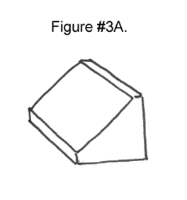
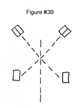
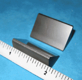
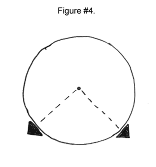
The simplest construction technique for a split kinematic couple would be to match one huge diameter ball and a set of split kinematic vees, with the two other couples of conventional. This would be an ideal approach, from the kinematic standpoint, as it would provide a simple design that is truly kinematic, but it would totally defeat the fundamental purpose of a kinematic clamp, which is to carry the payload. (See figure below) In addition, the cost of the very large, high quality ball, would be out of the question.
The sensible way to form the mating half of the couple is by using two spherical inserts or buttons on the second platform that simulates the contacts with one very large sphere. These spherical buttons must be of the proper radius to simulate one large diameter ball and they must be placed at the proper position, to make tangent contact with the inclined plane vee block surfaces. (See Figure #5A and Figure #5B.) Using this technique we end up with a truly kinematic system that is very mechanically stable.
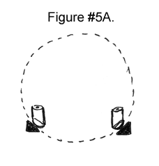
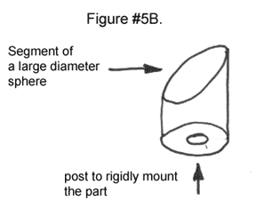
The cylindrical post mounted, spherical buttons are very accurate, quite rigid, easy to install and not expensive. The cylindrical post mounting arrangement has an added advantage in that there is no obstruction down centers of the upper platform, so that the upper platform can move over a rail when required. This approach is only slightly more expensive than the more conventional monolithic vee block designs.
