Bal-tec™ Home Ball Gage Technical Information Sheet
Ball Gage Technical Information Sheet
The Ball Plug Gage, Introduction
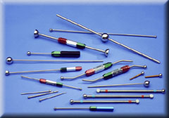
Using a ball mounted on a stem or handle to evaluate the diameter of a cylindrical hole is a widely used commercial process. The first question that must be answered in evaluating any measuring process is, "just what is the fundamental premise for the methodology?" To be reliable, every dimensional measuring process must be directly traceable to a fundamental principal of physics. The fundamental definition for the diameter of a sphere is a geometric figure with all points on the periphery equidistant from a central point.
This is the pedigree for the use of the Ball Plug Gage. A Ball Plug Gage will absolutely measure the true cylindrical diameter of any hole. If a ball of a well known diameter will pass through an internal cylindrical diameter, we can be absolutely sure that this internal cylinder is at least as large as that ball is in diameter. A lack of cylindrisity does not influence the ball plug gage's ability to measure true cylindrical diameter. Even if a cylindrical hole is bent or cambered, a ball gage will still faithfully measure the true cylindrical diameter of that hole.
A factor that is always involved in making dimensional measurements by physical contact is the surface quality of both the gaging body and that of the subject part. Physical contact between the surface of a Ball Plug Gage and the internal cylinder that it is measuring is strictly limited to an extremely narrow line of contact. This very narrow line leads to almost no friction, so that the ball literally falls through the hole. The fundamental nature of the physical process used to manufacture precision balls automatically gives the ball an ideal gaging surface that is less than 1.5 micro inches RA. During the ball making process, a group of ball blanks are rolled between two plates in the presence of abrasive slurry. This lapping process creates the micro inch quality surface.
Attaching the Stem to the Ball
Attaching the precision gage ball to the stem or handle of a Ball Plug Gage presents several problems. The ball can not be brazed or soft soldered on the stem, because the heat will change the size of the ball and drive it out of round. An excellent solution for attaching the ball is to glue the stem into a small diameter deep hole.
The 62HRC hardness of the gage ball makes it much too hard for conventional drilling. The problem of drilling an acceptable mounting hole in the gage ball can be solved by using modified Electrical Discharge Machining techniques. The first step in this process is to use a super dielectric or electrolytes in the EDM machines. This dielectric is made by emulsifying silicon oil and distilled water with a 900 watt ultrasonic cavitron. This combination of distilled water and silicon oil has an extreme resistivity of over eighteen million ohms per square centimeter.
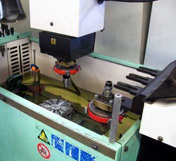
The high specific heat of the water in the emulsion carries away the heat generated by the electrical discharge, without it causing any distortion of the gage ball. The frequency of the electric discharge current is held very high, so there are literally millions of very small sparks that cut the hole. After the difficult job of cleaning the EDM'ed hole is accomplished, a pre-machined stem is glued in the hole in the ball. For this task, an extreme strength ceramic filled epoxy resin is used.
Nothing is simple: A test sample from every batch of the epoxy glue mix must be tested for hardness and tensile strength. These tests are required because we have had failures due to the very complex glue chemistry, and we will not risk sending defective products to our customers.
A Ball Plug Gage Used as a Calibration Standard
The very best setting master for calibration the diameter of other precision balls is a calibrated "Master Ball Plug Gage." The traceable uncertainty of the absolute size of our Ball Plug Gages is in the low micro inches. By using a master setting standard with the same geometry and the same physical properties as the balls to be measured, the most accurate possible comparison can be made. (Ball Gage Setting Master). When trying to calibrate a spherical test part with a setting master that is a flat parallel gage block, or a cylindrical pin gage, the differences in geometry of the master and the spherical ball will lead to vast transfer errors.
Bent Stems or Handles
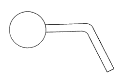
The Versatility of Ball Plug Gages can be dramatically improved, for certain applications, by bending the stem so that the gage ball is applied to the test part at other than right angles, to the handle. If a simple sketch providing the stem length and the angle is provided, we can supply the gage pre bent and ready to use.
Really Bent Stems
There are times when the stem that holds the gage ball needs to be bent up down and all around, literally. In this case the stem material needs to be dead soft "annealed," mild steel. For this very special application, the stem material must be specified as dead soft annealed wire when placing the order.
The Cylindricized Ball Plug Gage
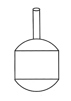
The spherical surface to be measured is sometimes down in the bottom of a restricted area. Reaching the surface to be measured requires that the major diameter of the Ball Plug Gage have a cylindrical section ground away. Even though this design is common place, every one of these gages must be custom made. The Cylidricized Ball Gage is also commonly used without a handle. Dimensions are commonly measured over the top end of the remaining ball. When the Cylindricized Ball Gage is used without a handle, the size and serial number is laser etched on the cylindrical diameter.
Internal Spherical Measurement
Measuring an Internal Spherical Cup
The most widely used method for measuring, both the size and the sphericity of an internal sphere is to use a Ball Plug Gage as a bluing master. The bluing technique consists of applying a very thin coat of Prussian Bluing to the test part or to the Ball Plug Gage and then rubbing the test part and the Ball Plug Gage together lightly. Prussian bluing is a deep dark blue pigment suspended in an oily base. Prussian Blue has nothing to do with Blue DYKEM®. Prussian Bluing is supplied in a small metal dispensing tube.
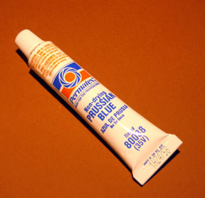
A little Prussian Bluing will go a long way, use it sparingly.
Tubes of Prussian Blue are available as our part number BL-960. ![]() .
Prussian Bluing will stain anything that it touches, including your fingers.
A good cleaning agent for Prussian Bluing is Isopropyl Alcohol. Small amounts of Isopropyl Alcohol are available from any drug store, where it is sold as Rubbing Alcohol.
.
Prussian Bluing will stain anything that it touches, including your fingers.
A good cleaning agent for Prussian Bluing is Isopropyl Alcohol. Small amounts of Isopropyl Alcohol are available from any drug store, where it is sold as Rubbing Alcohol.
Isopropyl alcohol is flammable, so it must be used with great care. When using the Bluing technique, there are two general approaches:
For method number one, you put a light coat of Prussian Bluing on the test part and then use the Ball Plug Gage to wipe the bluing off. This is the technique that is usually used to inspect ball bearing race ways.
For method number two, which is sometimes called printing, the Prussian Bluing is applied to the Ball Plug Gage and then transferred to the test part by rubbing them lightly together. This printing technique is the one that is usually used for evaluating internal spherical surfaces. When using the technique of transferring Prussian Bluing to the test part from the Ball Plug Gage, it is highly recommended that a satin finished Ball Plug Gage be used.
A Satin finished surface will hold a nice even, very thin layer of Prussian Bluing, while the usual shiny, slippery lapped surface, of a standard ball, will have a splotchy, thicker layer. After the satin finished Ball Plug Gage is very lightly coated with Prussian Bluing, the Ball Plug Gage is placed into the spherical cup and lightly rubbed and indexed.
- If the bluing hits at the very top rim of the spherical cup, then the spherical cup is smaller than the ball.
- If the bluing hits at the very bottom ring of the spherical cup, then the spherical cup is larger than the ball.
- If the bluing covers the entire surface of the spherical cup, then the ball is the same radius as the cup.
It is very hard to machine the spherical cup exactly the right radius so tolerances are often spelled out in the percentage of the spherical surface that blues in I.E. the spherical surface must blue into x.xxx diameter Ball Plug Gage 80%. Another approach is that the spherical cup must be larger than one ball size and smaller than another. The danger of this type of tolerancing is that the surface of the cup may be grossly out of sphericity but still measure good. Using the tolerancing that the ball must blue into the sphere a given percent is by far the best tolerancing approach.
The Length of the Ball Gage Stem
The standard length of the stem or handle on a Ball Plug Gage is three inches ( 76mm ), but a stem of any desired length can be provided at little or no increase in cost.
See the "Snake Ball Gage" as an extreme, example of the stem length.
Measuring Cross Holes with a Ball Plug Gage
The Ball Plug Gage has two big advantages over any other gage for this chore. The first is that the Ball Plug Gage will enter a hole at any angle and automatically self align to pass through the hole, and the second is that the small diameter stem can be bent at an angle so that the ball will enter the hole nearly perpendicular. The Ball Plug Gage makes the measurement of cross holes at any angle to the walls of a part routine instead of nearly impossible.
Measuring Cross Race Curve of Antifriction Bearings
A Ball Plug Gage is the ideal tool to use for measuring the cross race curve of ball bearings. It is standard industry practice to evaluate both the actual radius and the geometric quality of antifriction bearing races, with a Ball Plug Gage. Prussian blue is a dark blue pigment suspended in an oily base. Prussian bluing has nothing to do with Blue DYKEM®. Prussian Bluing is supplied in a small metal dispensing tube. Tubes of Prussian Bluing are available as our part number BL-960. The first step in measuring the cross race curve of the bearing race is to apply a very thin coat of "Prussian blue" to the surface of the bearing race way. The second step is to use the Ball Plug Gage to wipe off the Prussian bluing.
If the cross race curve of the bearing race is exactly the same radius of curvature as the Ball Plug Gage, the ball will wipe off all of the "Prussian Blue" and the entire width of the raceway will have a silvery metallic look. If the cross race curve of the bearing race, is larger than the radius of the Ball Plug Gage, the ball will wipe all of the Prussian blue off of the bottom or center of the bearing race and it will leave a gradually darker blue stripe going up either side, of the bearing race. If the radius of the bearing race way is smaller than the Ball Plug Gage, the ball will wipe all of the bluing off the upper rims of the raceway leaving, two silvery stripes at the top with a gradually darker blue stripe at the bottom.
In addition to the Ball Plug Gage's ability to measure the exact radius of the cross race curve, it will accurately depict the regularity of the cross race curve. The sphericity of the Ball Plug Gage is almost perfect, so it will accurately indicate variations in the cross race curve as indicated by the blueness of the pattern left in the raceway by the Prussian Blue. Although the values are somewhat subjective, by using a series of different diameter Ball Plug Gages very definitive results can be determined. We have used this technique with a large number of Ball Plug Gages to provide more reliable data on cross race curve than could be produced by all of the machinery and personnel in a large bearing metrology lab. Extracting reliable data on the quality of the cross race curve of antifriction bearings is difficult.
Measuring Fragile Parts with a Ball Plug Gage
The most delicate, fragile parts can be safely evaluated with Ball Plug Gages. There is a very gradual engagement between the Ball Plug Gage and the part as the gage is brought into physical contact with the test part, and then the same gradual disengagement as the gage is removed. The non destructive nature of using a Ball Plug Gage is one of the outstanding properties of this device.
At a recent trade show, we learned of couple of excellent examples of this property. In the first case, a customer rejected a large order of a precision aluminum part. The flat surface adjacent to a very precise hole was all dinged up. This damage was done, by an inspector trying to get a cylindrical plug gage into the hole. All of these parts had to be fly cut a second time to correct the problem. In the second case, $5,000 worth of precise orifices had been scrapped by an inspector who used a cylindrical plug gage to measure the diameter of the narrow orifice, instead of the Ball Plug gage that was specified on the operation procedure.
A Handle for the Ball Plug Gage
Unless there are special needs, we supply a standard AGS (American Gage Society) design handle for our Ball Plug Gages. This handle consists of hexagonal aluminum tube with a hexagonal, threaded cap, on the end. The stem that the ball is mounted on is held in place by a collapsible bronze bushing. When the hexagonal aluminum cap is rotated clockwise, it compresses the bronze bushing thus locking the stem of the ball plug gage rigidly in place. The hexagonal aluminum caps are color anodized green for the GO end of the gage and red for the NO GO end of the gage.
Ball Plug Gages are most often supplied in a dual configuration, with a GO Ball Plug Gage on one end and a NO GO Ball Plug Gage on the other end. We also have these gage handles available in single ended configurations. The size of each ball plug gage is engraved into the handle of the gage. A nominal amount of additional information will be engraved on the handle at no additional cost. If an extensive amount of data must be engraved, it will require "Laser Marking" which may require a small surcharge.
Material for Ball Plug Gages
The conventional material used to manufacture Ball Plug Gages is a chromium alloy bearing quality steel. This very high carbon alloy steel is hardened to 62 H.R.C. (Hardness Rockwell "C scale"). This material is very stiff. It has a Young's modulus of elasticity of 30,000,000 PSI and a Poisson's ratio of 0.23. For some heavy use applications, the balls on the Ball Plug Gages are made of extremely hard, wear resistant, tungsten carbide. When tungsten carbide balls are used, the balls are usually brazed on to the stem. Ball Plug Gages made with tungsten carbide balls are available in the same high quality as the chrome steel balls.
Measuring Out of Round Holes
The holes that are used to hold fasteners in modern aircraft must be inspected for out of roundness. The simple test used for this evaluation is to rotate a No Go Ball Plug Gage that has two parallel ground flats, in the mouth of each hole. If the hole is out of round, the No Go Ball Plug Gage will fall through the out of round hole.
Measuring Shallow and Extremely Shallow Bores and Counter Bores
By removing the end of a Ball Plug Gage almost to its centerline, it can be used to very accurately measure bores and counter bores that are extremely shallow. The go Ball Plug Gage makes a very distinct click when entering the shallow hole, so that determining acceptable and not acceptable parts is a very black and white situation. The amount of centerline overhang must be kept to a minimum on the no go gage.
Rod End Bearings Measured with a Ball Plug Gage
A modified Ball Plug Gage is the best way to evaluate the internal spherical diameter of Rod End bearings. This modified Ball Plug gage, consists of a standard gage with two flats machined parallel to the stem or handle. These flats are machined so that the remaining sphere will safely enter the loading slot of the rod end bearing. A "go" and "no go" set of these modified Ball Plug Gages is required.
The Snake Ball Plug Gage
Measuring the Inside Diameter of Tubing and Pipe with a Ball Plug Gage.
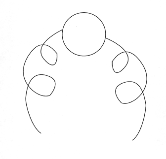
A simple solution for measuring the diameter of the full length of a piece of tubing or pipe is to pass a ball of known diameter through the diameter that is to be evaluated. The conduit to be evaluated can be straight, all bent up or full of joints, it doesn't matter. Previously, they used what was called the "puff test," for conduits on U.S. Navy submarines. This test consisted of putting a minimum sized ball that should easily pass through a pipe or tube in one end of each pipe or tube and then applying a few pounds of air pressure.
This puff of low pressure air would send the ball speeding through the tube and out the other end. This procedure went on for some years, until one day a ball got jammed in a tube down in the guts of a submarine. They had no idea where the ball was. It took days to cut out the entire piece of tubing and replace it.
When we were approached for a solution to this new dilemma, we quickly invented the "Snake Ball." This simple device has a continuous wire or cable going all the way through the center of the ball and coming out both sides. Using the Snake Ball, you are able to pull the ball into the tube and then you can pull it back out, all very inexpensively and with complete reliability.
For some fussy applications we provide an additional smaller diameter ball on the very ends of the wire. This provides a smoother passage of the wire past the joints in the conduit. For some applications with delicate surfaces, we supply the "Snake Ball" with wire cable that is plastic covered.
The Stem Material For Ball Plug Gages
The stem material used to hold the gage ball is typically drawn and straightened, mild steel. The Young's modulus of elasticity or stiffness of mild steel is very high at 30,000,000 pounds per square inch. The other commonly used material is 300 series stainless steel, which has a Young's modulus of elasticity of only about 18,000,000 pounds per square inch.
This means is that mild steel is literally one third stiffer than 300 series stainless steel. An additional advantage to the mild steel is that it has exactly the same thermal coefficient of expansion as the 52100 chrome alloy steel that the gage ball is made of. For this reason, the stem material will have no tendency to distort the size or the shape of the ball when there are temperature irregularities.
The Speed of Measurement with a Ball Plug Gage
The speed with which the size of a hole can be determined with a Ball Plug Gage, compared with any other technique, can be a hundred times faster. This comparison was shown when measuring a large number of small holes in a big sheet metal part. This large part was a piece of an aircraft skin. This part had hundreds of small diameter holes, every one of which had to be measured, for size and tested for out of roundness. The same very fast technique can be used to measure for any out of round holes. The no go Ball Plug Gage which has two parallel flats is simply places in the mouth of the hole and rotated. If the hole is out of round, the Ball Plug Gage will literally fall through it.
