Bal-tec™ Home Mechanical Clamping of Kinematic Couplings
Mechanical Clamping of Kinematic Couplings — Mechanical Pre Loading of Kinematic Couplings
There is a very simple mechanical clamping technique for use on Kinematic couplings that can be used for fail-safe, high load carrying, off axis loading and vertical Kinematic couplings. This approach is very viable in high vibration environments.
The Pre Load Kit
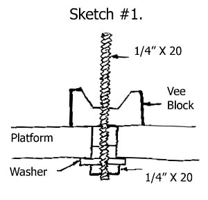
The design consists of all of the components required for the Kinematic coupling as well as those for the clamping system. The system uses three of our standard, cylindrical post-mounted vee blocks (part number 75-VB-CBM) [3 pieces required] mounted on the lower platform. See Kinematic Catalog 105B , for the dimensions and full details. These are used with three pieces of one-quarter inch ( 1/4", 0.25", 6.35 mm) by 20 threads per inch, continuous threaded stock. This threaded stock projects up through the top of the Kinematic platform and down through the lower platform.


Above the vee block the ¼"-20 continuous threaded stock passes through a clearance hole in the upper three quarter inch ( ¾", 0.75", 19 mm ) diameter Kinematic sphere (our part number 75-270-CH) [3 pieces required] and on through the upper platform. The two Kinematic platforms are held rigidly together by a one-inch (25.4 mm) diameter knurled clocking nut (our part number 250-20-CN) [3 pieces required]. This device is supplied with a heavy washer and a wing nut, to lock the clocking nut, for use in moderate vibrational environment. When situations of severe vibration are encountered a special clocking nut, fitted with our barn door clamping system may be required. Please contact our engineering department. This device includes a ball thrust bearing which decouples the torque of the clocking nuts rotation. This nut transfers the clamping force through a self-aligning three quarter inch (19 mm) diameter spherical tilt (our part number 75-ST-270) [3 pieces required]. The clocking nut has a timing line engraved on the face, so that the applied force can be repeated, by simply clocking the position of this engraved line.
A complete set of the Kinematic coupling hardware and the mechanical clamping kit, with all three sets of the components is available as (our part number FS-KIT-750), (see sketch #3). Some advantages of using this clamping technique is that a much higher clamping force can be applied because three screws are utilized instead of one. These three clamps are placed far out towards the edges of the platform, leaving the center of the platform for mounting the payload. The mechanical stability of the three-clamp platform is much better because the clamping force is applied as far out as possible. The downside to this design is that there are four lose pieces of hardware that must be assembled for each clamp.
Bottom Mount
The mechanical clamp can be mounted so that the clamping screw projects out the bottom side of the platform. This leaves the front face clear of any protrusions that would interfere with mounting the payload. If the end of the clamping assembly is obscured by this inverted mounting, it may be advisable to use a hex “jam nut” instead of the usual wing nut supplied.
Clamping Small Platforms
On small platforms, a single clamp, located in the center of the platform may suffice. Using only one clocking nut with one spherical tilt and a single piece of ¼-20 continuous threaded stock, located in the exact center of the Kinematic coupling good results may be achieved. (our part numbers 250-20-CN and 75-ST-270).
Spring Loading
Spring-loaded clamping may be desirable in some special applications. When this option is used it is only necessary to add a spring of the proper rate and a washer between the clocking nuts and the spherical tilt, or between the bottom of the spherical tilt and the upper platform.
Summary
The complete three piece set of Kinematic coupling hardware and the three-element fail-safe Kinematic clamping kit is available as (our part number FS-KIT-750). It consists of the following:
- Three pieces of (our part number #75-VB-CPM), the cylindrical post mounted vee block. See page 19 of our Kinematic catalog 105B for design details.
- Three pieces of (our part number 75-270-CH), which is the three quarter inch diameter Kinematic sphere with a .270-inch (6.86 mm) diameter center hole. See addendum to catalog 105B.
- Three sets of (our part number 75-ST-270), the three-quarter inch (19 mm) diameter spherical tilt.
- Three pieces of our one-quarter inch (6.35 mm) by 20 continuous threaded stock that are 9 inches (229 mm) long. You can cut these extra long pieces to the desired length when you make the assembly.
- Three pieces of one-quarter inch (6.35 mm) by 20 threads per inch heavy duty hex nuts.
- Three pieces of heavy duty machine washers, one inch (25.4 mm) O.D. by one-quarter inch (6.35 mm) I.D.
- Three pieces of a one-inch (25.4 mm) diameter knurled clocking nut (our part number 250-20-CN) including the ball thrust bearing, a washer and a wing nut.
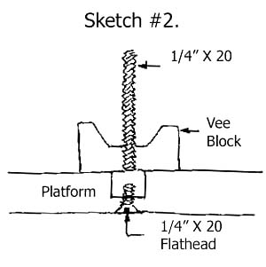
- Three pieces of screwdriver slot-one quarter inch (6.3 mm) by 20 flat head screws by three quarter inch (19 mm) long that are used if the alternative method (shown in sketch #2) is used to clamp the vee block to the lower platform.
See also, Magnetically Preloaded Kinematic Couplings .
