Bal-tec™ Home All Probe Characterization Spheres
All Probe Characterization Spheres
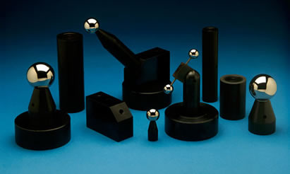
Probe Characterizing Spheres (aka probe calibration spheres, probe character sphere or datum spheres) are used to evaluate and determine compensation needed for errors in C.M.M. measuring probes. Most errors and problems on C.M.M.s are in the probe. This should be the first measuring device purchased to check the C.M.M.
How to Choose the Best Probe Calibration Sphere for Your Application
Sphere Diameter
The first consideration is to determine what diameter should the master calibration sphere be?
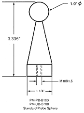
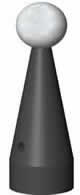
On most modern C.M.M.'s the probe fitting software will accept almost any diameter spherical master. The most common master spheres have been one inch, ( 1.00", 25.4 mm ), and three quarters of an inch, ( 3/4", 0.75", 19.05 mm ); but 28 mm (1.102 inches) and 30 mm (1.181 inches) diameter have become more popular as C.M.M. technology has taken on a more European focus.
The more popular sizes of master calibration spheres are less expensive. Changing the master calibration sphere diameter will not compromise the C.M.M.'s performance in any way. When using very small diameter spherical contacts on the measuring probe, choose much smaller diameter master calibration spheres to accurately characterize these small diameter contacts. The three most popular diameters for the master calibration spheres for smaller diameter probes are 4 mm ( 0.157 inch ), 6 mm (0.236 inch ) and 10 mm ( 0.3937 inch ). The smaller diameter master spheres are used to calibrate the smallest probe spheres and so on with the larger diameters. The problem of serious wear of the small diameter master spheres, due to the high contact force, makes it almost mandatory that these small diameter spheres be made of tungsten carbide. This is a necessary compromise because there will be some built in error due to the high stiffness of the T.C. material.
Sphere Material
The choice of material for the master calibration sphere can be of great importance, depending on the contact force of the measuring probe and its spherical diameter. The important factor in the choice of the material for the master calibration sphere is its stiffness. When the probe contacts the master calibration sphere, there is considerable Hertzian elastic deformation of both the master calibration sphere and the spherical contacts of the probe. The amount of these deformations depends mainly on the probe sphere diameter and the contact force of the measuring probe. The smaller the probe ball, and the higher the measuring force, the more elastic deformation will occur. If we use a very stiff material like ceramic or tungsten carbide for the master calibration sphere, and then measure ordinary materials such as aluminum or steel; we will loose appreciable accuracy. This built in error will be greater with the high measuring force typical of many of the modern scanning probes and will be higher for small diameter probe spheres than for the larger ones. The nearer the stiffness of the master calibration sphere matches the stiffness of the part being measured, the less error will result. For this reason, steel calibration spheres have been the order of the day until recently.
If the master calibration spheres are replaced in kind, all standard diameters of ceramic and tungsten carbide master calibration spheres are available.
Mounting the Ball
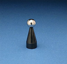
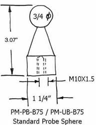
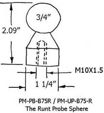
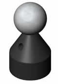
The next variable is choosing the design for the post used to hold the master calibration sphere. The one important word here is the rigidity of the post. What is needed, is a robust stiff structure that will still allow full access of the master calibration sphere by the measuring probe. When simple vertical or horizontal probes are being calibrated, the standard very rugged "PB" series calibration spheres on a very stiff post are the most accurate and the least expensive choice.
Slim Calibration Sphere
When calibrating more complex articulating probes and compound star probes, more complete access to the master probe calibration sphere is required. The first and least expensive of the complex probe calibration devices is the "Slim Probe" Calibration system. It consists of one or more master calibration spheres mounted on very slender, extremely high stiffness cermet rods. These one eighth of an inch 0.125" (3.2mm) diameter, extremely rigid cermets rods allow almost complete access to the periphery of the master calibration sphere or spheres. This more complex design and more expensive components cost about a 20% premium, over the standard PB series probe calibration spheres.
Star and Tree Probes
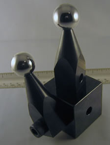
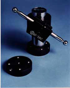
When the fastest most accurate calibration of complex star and tree probes is required, the device to specify is the "Star Probe Calibration Device". This arrangement uses five exactly matched master calibration spheres. One sphere is positioned vertically, and the other four are arranged horizontally at ninety-degree increments (see details of this device in the technical data sheet under C.M.M. products). The very rigid three quarter inch, 0.75" (19mm), mounting posts that hold the five master calibration spheres are securely fastened to a robust two inch, 2" (50.8 mm), diameter pole, that is in turn fastened to a four inch, 4" (101.6 mm), diameter ultra stable platform. The significance of this design is that the area of one master calibration sphere that is covered up by a support post is exactly opposite another matching calibration sphere, where that area is completely exposed. Subtract the fixed distance between the two spheres to get a 100% calibration of even the most complex probes.
Small Probe Calibration
Calibrating measuring probes with very small diameter contact tips requires small diameter master calibration spheres mounted on small diameter posts.
These parameters become even more critical when small diameter complex probes are used in the scanning mode. For these applications, a petite version of the star probe calibration device is available (see details under C.M.M. products).
Optical Probe Calibration
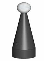
Optical probes form a very broad spectrum of devices, but they respond well to rather limited range of master calibration devices. The one "no no" for optical calibration devices is bright shiny artifacts. The least expensive calibration sphere is the satin finished stainless steel ball. Some optical probes respond very well to satin finished titanium, which has a very flat gray surface.
The most popular master calibration sphere for optical probes is satin finished aluminum oxide ceramic, which is very white but very dull. All of the metal balls suffer from the tendency to get burnished stripes on the surface that affect the calibration. This burnishing is caused by almost any physical contact with hard materials. This does not happen to the aluminum oxide ceramic. The very white surface of the ceramic ball gets dirty very quickly, but it can be easily cleaned with coarse hand soap. Very short Ball Bars (Dumbbells), with satin finished ceramic balls are a very popular calibration device. The post next to the balls is black oxide coated so they don't effect
To facilitate the holding of these very short Ball Bar (Dumbbell)s, we have developed the "Hammer." (See the technical data sheet under C.M.M. products). The Hammer has a right-angled post that is used to hold the Ball Bar (Dumbbell) in our standard clamping hardware. The characterization spheres are often ordered with and used with risers ( extensions ) and Dual Threaded Adaptor Screws.
Repair
We will remove a worn or damaged probe calibration ball and replace it with a brand new ball of the highest quality at a very reasonable price.
Custom
We will be pleased to quote you custom manufactured probe calibration spheres. These devices can be to your design, or we can replicate an existing product.
Calibration
We will inspect your probe calibration spheres for size and roundness. We will provide you with a long form inspection report that is traceable to N.I.S.T. for $65.00 each.
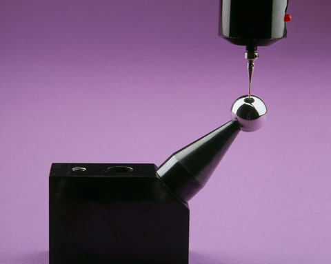
Using the Probe Characterizing or Calibration Sphere
This Probe Characterizing technique uses computer software and an extremely high quality spherical artifact of a well known diameter to calibrate the radius of the contact tip. It will characterize geometry errors of the measuring probe (probe lobbing), it will compensate for bending of the probe stem and a broad range of other elastic deflections or bending moments throughout the machine. The sphere is very rigidly fixed to the C.M.M. table for this test. In effect, the C.M.M.'s computer is told that it is measuring a perfect sphere of a specific diameter and that any departure from this ideal form should be corrected in all future measurements. Some C.M.M. software is written around a specific master sphere diameter while other software is open to selection by the user.
The most widely used sphere diameter is one inch (25.4mm) but 3/4 inch (19.05mm) is also widely used. In our experience down to about 10mm (.3937 inch) diameter, the smaller the master sphere used, the more accurately probe lobbing will be compensated for. This correction ends up being a simple adjustment in the apparent radius of the contact tip of the measuring probe.
Repeatability Test
This same spherical artifact makes an excellent Coordinate Measuring Machine repeatability test device. Its position on the table and its diameter are simply measured a considerable number of times (usually ten to twelve), and the results are compared. Each measurement consists of a small number of well distributed hits. Any variations in the measurements reflect a lack of machine repeatability. Valuable information about specific machine performance can be learned by looking at the end positions of individual axii. Note that this test must be performed as quickly as possible to avoid the influence of temperature drift.
The 2" By 2" Block
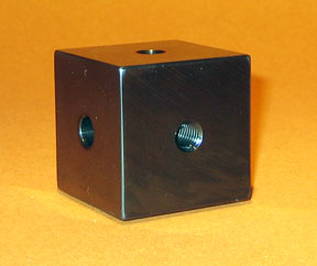
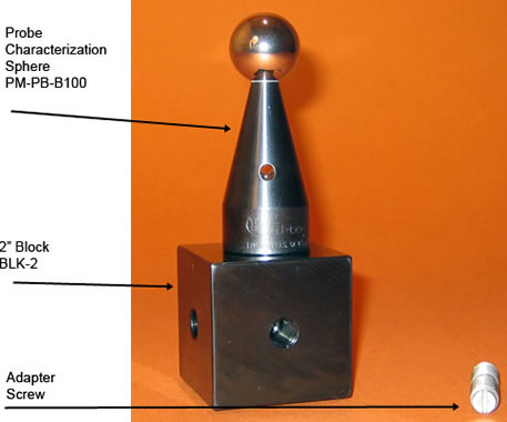
We offer the 2 inch by 2 inch universal mounting block, Part Number BLK-2, as an accessory for use with the probe calibration sphere hardware. The four threaded tie down holes are M10-1.5 thread. A through mounting hole with clearance for 10mm or 3/8 inch tie down bolt is provided. This approach to tie down allows the two inch square by two inch high block to be clamped down in any angular position.
The simplest application is to use it as a 2 inch riser to hold any of our probe calibration spheres. The 2" by 2" block can be used to mount any of our probe calibration spheres at right angles to the C.M.M. table. Mounting up to five of our standard probe calibration spheres creates an excellent star probe calibration device. Leaving it mounted on the CMM table with several of the calibration spheres attached provides a monument that will quickly provide proof of performance as an interim evaluation of your C.M.M.
Five sphere calibration spheres mounted on the 2" by 2" block, creates ten inter-sphere dimensions that are, in effect, ten unique length Ball Bars. The assembly of these 5 devices is a "pretzel" that exercises every function of your Coordinate Measuring Machine. Having the several extra probe calibration spheres available will provide you with the in house hardware to perform frequent temperature drift evaluations. Our entire family of probe calibration hardware is designed to be compatible with the 2" by 2" blocks.
Pricing
| Part # | Description | Price | Purchase |
|---|---|---|---|
| BLK-2 | 2 INCH BLOCK | $162.00 | |
45 Degree Angle Block Part Number: BLK-45
| Downloads | ||
|---|---|---|
| Solidworks | IGES | |
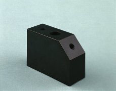
The 45 Degree Angle Block ( Part Number BLK-45 ) is used to hold Probe Characterizing Spheres inclined at 45 degrees, so they are more accessible for C.M.M. calibration. The block may be located in an out of the way place on the CMM table, while projecting the characterizing sphere out into the working zone of the machine.
This robust steel angle block is 3-1/2 inch ( 3.5", 88.9mm ) long by 1-1/2 inch (1.5", 63.5mm ) high and 1-1/2 inch ( 1.5", 38.1mm ) wide. Two tapped holes that are M10 inch diameter are provided to secure the characterizing sphere's 1-1/4 inch ( 1.25", 31.75mm ) diameter post. One tapped hole is provided in the center of the 1-1/2 inch ( 1.5", 38.1mm ) long 45 degree land, and one is provided in the top surface near the end opposite the 45 degree angle.
The base surface that locates this 45 degree block has areas of the surface relieved to leave three mounting pads. These pads are lapped flat and coplanar to form a stable clamping surface. A counterbored hole is provided through the height of the block. Using this counterbored hole, the 45 degree angle block is clamped solidly in position by 3/8 inch ( 0.375" ) or a 10 mm socket head cap screw. This 45 degree Block is designed to be used with the 4 inch ( 101.6 mm ) diameter steel platform, Part Number PLT4, see Technical Data Sheet The 45 degree Angle Block is supplied with an attractive black oxide finish which resists corrosion. The 45 degree Angle Block is generally purchased with dual threaded adaptor screws and a probe characterization sphere.
Pricing
| Part # | Description | Price | Purchase |
|---|---|---|---|
| BLK-45 | BLOCK, 45 DEGREE | $130.00 | |
The Abalone
The Abalone ( Part #10140 ) was originally developed as a clamping device for holding the Anchor and Ball Bar (Dumbbell) combinations on the tables of Coordinate Measuring Machines. Since then, it has found wide use for a variety of clamping and work holding tasks on C.M.M.s surface plates and machine tools. The Abalone is a powerful vacuum hold down device. When used with a good vacuum pump, the five inch diameter (127mm) base will provide over 290 pounds (131kg) of clamping force. The one and one quarter inch (31.75mm) thick aluminum device weighs only two pounds (.9 kilograms). It is hard coated and the base is precision lapped flat for good mechanical stability, long wear and to form a good vacuum seal that will assure the highest clamping force. A M10x1.5 threaded hole is provided in the top center of the Abalone to attach the Anchor. For added utility, there are four M10x1.5 drilled and threaded holes around the outer edge of the upper surface. These threaded holes facilitate the rigid mounting of other tooling.
Pricing
| Part # | Description | Price | Purchase |
|---|---|---|---|
| 10140 | ABALONE, 5" DIAMETER X 1.5" THICK | $165.00 | |
The Address Spheres
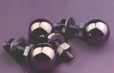
When three of these devices, also known as a tooling ball, (Part #A40320) are rigidly attached to diagonal corners of a Coordinate Measuring Machine pallet, it will exactly define the pallet's three dimensional address or position on the measuring machine table. The relative position of these threaded tooling balls defines the fixed location points that are used to exactly position the test part on the pallet system. This approach to locating these devices actually allow a pallet to be randomly positioned anywhere on the C.M.M. table, and yet the computer has a perfect knowledge of the test part's true three dimensional position. This location is retrieved from the data that was stored during the original measurement of the test part some time earlier.
The three exactly matched hardened stainless steel balls are three quarter inch ( 1.9 cm ) diameter. They are precision lapped spherical within less than five microinches and the surface is polished to a fraction of a microinch. The sphere is securely attached to the head of a short 1/4 inch (6.3 cm) diameter stainless steel bolt that has twenty threads per inch. To prevent a slight bump from separating the ball from the bolt, a 1/8 inch (3.2 mm) diameter pin extends well up into the ball and down into the bolt. A stainless steel washer and a jam nut are supplied with each threaded address sphere to rigidly fix their position on the pallet. In addition to their use for locating the position of a pallet on the C.M.M. table, these devices make an excellent measuring artifact and two or more of them left mounted on a pallet can form an interim checking device. A large array of these balls can be mounted on a simple piece of metal plate to construct a very high quality ball plate for Coordinate Measuring Machine Evaluation. When building a large artifact using many balls, the balls should be ordered as a single master set so that all spheres will be exactly the same diameter.
Address Sphere Pricing
| Part # | Description | Price | Purchase |
|---|---|---|---|
| A40320 | ADDRESS SPHERES, SET OF THREE | $151.00 | |
The Big One
Part Number BO-PM-B200
| Downloads | ||
|---|---|---|
| Solidworks | IGES | |
| N/A | ||
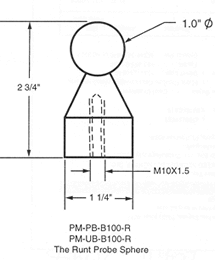
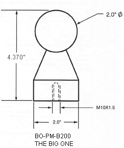
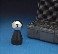
The "Big One" ( Part Number BO-PM-B200 ) is a giant 2.00 inch (50.8mm) diameter precision sphere mounted on a rugged 2.00 inch (50.8mm) diameter by 2-1/2 inch (63.5mm) high steel post. It was developed for the evaluation of Computer Numerically Controlled Machining Centers according to ANSI/ASME B 5.54.1992. It is also used as a probe characterizing sphere on some Coordinate Measuring Machines. The large target is particularly well-suited for use on big machines and on multi-spindle machines. Some of these tests include Machine Tool Repeatability, Temperature Variation Error, Hysteresis, Feature Accuracy, Pallet Change Repeatability, Tool Changer Repeatability, Drift, Vibration and Compliance.
The surface area of this 2.00 inch ( 50.8mm ) diameter sphere is 12.566 square inches ( 319.19 square mm ) which is four times the 3.1416 square inch (79.797 square mm) area of the standard 1.00 inch ( 25.4 mm ) diameter sphere commonly used. The 2.00 inch (50.8mm) diameter precision sphere is made of very fine grain high chrome, high carbon stainless steel that is hardened to 58 HRC for wear resistance and cold cycled for long-term dimensional stability. This large diameter component is lapped spherical within 5 millionths of an inch (127nm) and has a surface finish below 0.7 micro inches (17.78 nm) Ra. The exact diameter of the sphere can be certified to 10 millionths of an inch (254nm).
This design uses a unique high strength connection to join the precision sphere to the post. An Electrical Discharge Machine ( EDM ) is used to drill a concentric hole deep into the already finished sphere. This space age process uses millions of tiny bursts of electrical energy to erode a hole into the precision sphere without affecting the original quality. The end of the post has a corresponding hole drilled in it. As the high strength glue is applied to the assembly, a steel pin is inserted between these holes to form a very strong connection.
The flat base of the mounting post is recessed to leave an annular ring forming a stable connection for the sphere. The post of the "Big One" is provided with an attractive black oxide finish that resists corrosion. A 1/4 inch (6.35mm) diameter clearance hole is cross-drilled through the post and a high tensile stainless steel pin is provided to tighten and to remove the device from its mount. A M10 x 1.5 tapped hole is machined in the center of the flat base of the post to provide a strong means of attachment. This configuration is standard throughout the product line so that all components are interchangeable.
Pricing
| Part # | Description | Price | Purchase |
|---|---|---|---|
| BO-PM-B200 | BIG ONE, THE, 50.8 MM, 2 INCHES, 2.5 INCH POST | $431.00 | |
| BO-PM-SAT-B200 | BIG ONE, THE, SATIN FINISHED 50.8 MM, 2 INCHES, 2.5 INCH POST | $431.00 | |
| BO-EP-3 | BIG ONE, EXTENSION 3 INCHES, 2" DIAMETER | $37.40 | |
| BO-EP-6 | BIG ONE, EXTENSION 6 INCHES, 2" DIAMETER | $40.70 | |
CMM Probe Standard Extensions
Standard Extensions for Probe Characterizing, Part Numbers P-EP-2, P-EP-3, P-EP-6, BO-EP-3 & BO-EP-6, Extensions for CMM Probe Characterization Spheres
Standard Extensions ( risers ) raise and extend C. M. M. Probe Characterizing and C. N. C. Target Spheres. They are also used to securely couple measuring devices to the C. M. M. or C. N. C. table.
| Downloads | |||
|---|---|---|---|
| Part # | Solidworks | IGES | |
| BO-EP-3 | |||
| BO-EP-6 | |||
| P-EP-2 | N/A | N/A | N/A |
| P-EP-3 | |||
| P-EP-6 | |||
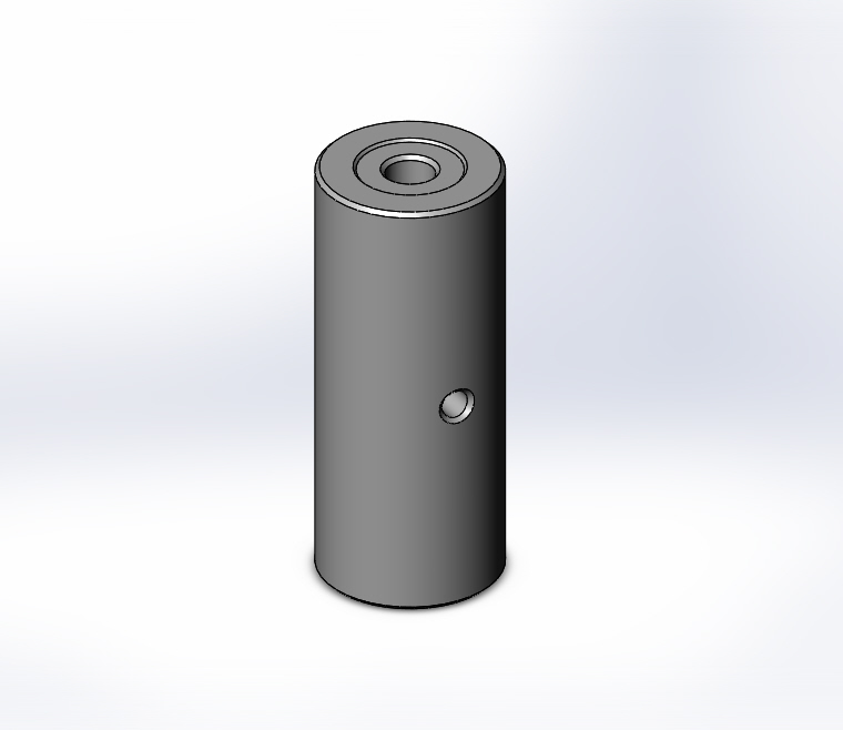
Three standard lengths of this version are available. The 2.00 inch (50,8mm) long version (Part Number P-EP-2), 3.00 inch (76.2mm) long version ( Part Number P-EP-3) and the 6 inch (152,4mm) (Part Number P-EP-6). The 1-1/4 inch ( 31.75 mm ) diameter extension posts have a 3/16 inch ( 4.76 mm ) clearance hole cross-drilled through the post diameter.
A high tensile stainless steel pin that passes through this hole is used to tighten and to remove the device from its mating part. Extensions for "The Big One"( Part Number BO-PM B200 ) are 2.00 inches ( 50.8 mm ) diameter to match its post. Two standard lengths of this version are available. The 3.00 inch ( 76.2 mm ) long version ( Part Number BO-EP-3 ) and the 6.00 inch (152.4 mm ) long version (Part Number BO-EP-6). The 2.00 inch ( 50.8 mm ) diameter extension posts have a 1/4 inch ( 6.3 mm ) diameter clearance hole cross-drilled through the diameter of the post. A high tensile stainless steel pin that passes through this hole is used to tighten and to remove the device from its mating part. Both ends of all extension posts are drilled and tapped M 10 x 1.5. This configuration is compatible with our full line of accessories. The center portions of both of the flat ends of all extension posts are recessed to leave annular ring. This flat ring forms a stable connection with the mating parts. All extensions are provided with an attractive black oxide finish which resists corrosion.
Pricing
| Part # | Description | Price | Purchase |
|---|---|---|---|
| BO-EP-3 | BIG ONE, EXTENSION 3 INCHES, 2" DIAMETER | $37.40 | |
| BO-EP-6 | BIG ONE, EXTENSION 6 INCHES, 2" DIAMETER | $40.70 | |
| P-EP-2 | EXTENSION, 2 INCHES, 1 1/4" DIAMETER | $38.15 | |
| P-EP-3 | EXTENSION, 3 INCHES, 1 1/4" DIAMETER | $38.15 | |
| P-EP-6 | EXTENSION, 6 INCHES, 1 1/4" DIAMETER | $39.44 | |
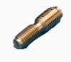
Dual Threaded Adaptor Screws
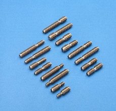
We carry a full line of Dual Threaded Adaptor Screws which have a different thread on each end. These threaded adaptors will match all of our Coordinate Measuring Machine evaluation and fixture building devices to the threads in the table of any C.M.M. or competitor's pallet system. The short version of these threaded adaptors (Table #1) have an overall length of 1.5 inches (38.1 mm) and each of the threads is 3/4 inch (19 mm) long, except the 1/4 inch-20 to M10 x 1.5, where the 1/4 inch diameter is only 1/2 inch (13 mm) long.
Pricing
| Standard Short-Threaded Adaptor: Table #1 | ||||
|---|---|---|---|---|
| Part # | Table Thread Size | Component Thread Size | Price | Purchase |
| S-8M-10M | M 8 x 1.25 x 3/4" ( 19 mm ) | M 10 x 1.5 x 3/4" ( 19 mm ) | $18.43 | |
| S-10M-10M | M 10 x 1.5 x 3/4" ( 19 mm ) | M 10 x 1.5 x 3/4" ( 19 mm ) | $18.43 | |
| S-12M-10M | M 12 x 1.75 x 3/4" ( 19 mm ) | M 10 x 1.5 x 3/4" ( 19 mm ) | $18.43 | |
| S-250-10M | 1/4" - 20 x 1/2" ( 13 mm ) | M 10 x 1.5 x 3/4" ( 19 mm ) | $18.43 | |
| S-312-10M | 5/16" - 18 x 3/4" ( 19 mm ) | M 10 x 1.5 x 3/4" ( 19 mm ) | $18.43 | |
| S-375-10M | 3/8" - 16 x 3/4 ( 19 mm ) | M 10 x 1.5 x 3/4" ( 19 mm ) | $18.43 | |
| S-500-10M | 1/2" - 13 x 3/4" ( 19 mm ) | M 10 x 1.5 x 3/4" ( 19 mm ) | $18.43 | |
Because these Dual Threaded Adaptor Screws get such heavy use, we machine a reduced-diameter on the very ends to avoid damaging the thread. The two threads have an undercut in the center to allow either of the threads to be tightened fully without any chance of binding. The Dual Threaded Adaptor Screws will not rust because they are manufactured from a very corrosive resistant type 18-8 Stainless Steel. The highest quality threads with increased tensile strength are produced by cold rolling the thread forms. There is a screwdriver slot provided at the end of each thread of the short version and in the long threaded end of the long version. With the aid of a coin or screwdriver, the Dual Threaded Adaptor Screw can be securely tightened into its mating part. The long version of these Dual Threaded Adaptor Screws have an overall length of 2.5 inches (76.2mm). The table, or short end thread, is 3/4 inch (1.9cm) long; and the M10x1.5 thread is 1.75 inches (44.5 mm) long, except the 1/4 inch-20 to M10x1.5, where the 1/4 inch diameter thread is only 1/2 inch (13mm) long.
If one of these fourteen combinations does not meet your requirements, we will be pleased to supply any other combination on special order.
SELECT Error: Access denied for user ''@'localhost' (using password: NO)