Bal-tec™ Home Fail Safe Coupling
Fail Safe Coupling

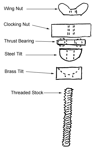
There are times when the integrity of a kinematic coupling must be assured. In these cases, the most straight forward approach is to secure the two platforms together with a threaded fastening system, or a multiple fastener system. In the simplest form, you will have a nut on a threaded shaft, tightened in place and locked down.
The clamping mechanism will need adequate clearance around the threaded shaft to allow for any misalignment in the “X” and “Y” axii. A spherical tilt will also be required, adjacent to the clamping nut, to compensate for any rotational or tilt errors around the “Z” axis. To provide “Z” axis dimensional repeatability, the nut should have an indicating or clocking mark, so that it can be tightened to the same exact place, time after time.
In addition, there will usually be a jam nut to lock everything in place. On sophisticated systems, there will need to be an antifriction thrust bearing to decouple the torque associated with tightening the clocking nut.
Positive Mechanical Preload
The same exact component parts and techniques that are used for “fail safe” applications will provide a mechanical preloading for the kinematic system.
There is another facet of the fail-safe concept, that can be employed when the very highest level of assurance is required. By using a resistance chain the actual physical contact between all six points of the kinematic coupling can be reliably measured. The only factor that is unique with this process, is that the individual vee block components of the kinematic coupling must be electrically isolated from each other. The typical components used in this type of coupling are six separate split vee blocks with an electrical connection and three balls or spheres. Typically, the resistance chain is a simple series circuit, between the vee block elements, incorporating a sensitive OHM meter with the balls acting as shorting bars, that connect the split vee blocks electrically.
More Information
For more information, and to order the coupling, see: Mechanical Clamping.
