Bal-tec™ Home Build C.M.M. Pretzel with Off the Shelf Parts
Build C.M.M. Pretzel with Off the Shelf Parts — Build Your Own C.M.M. Artifact — for C.M.M. Evaluation, Built From Off the Shelf Parts
Is your Coordinate Measuring Machine software cooking the collected data, or is it giving you cool rational results? The first thing to look at in this evaluation is the input data itself. In spite of what some operating instructions suggest, three data points do not a feature define. The accuracy of both the character and the Cartesian position of a simple feature, improves steadily with up to about seventeen hits, so your first opportunity to improve evaluation is to take enough measurements.
Using an Ultra Precise but very simple Ball Bar, all of the Coordinate Measuring Machines basic geometry errors can be fully evaluated. A step standard or gage blocks can be used to evaluate the three or more basic scale errors. You may note, or even object to the absence of a laser being used for any of these evaluations. We feel strongly that a mechanical contact machine must be evaluated by making physical contact with physical calibration artifacts. If this is not done the meriod elastic deflections that always occur with physical contact, will not be factored into the evaluation.
Now that the basic properties of the machine have been evaluated the real world measuring problems begin. This is the measuring of all of the different geometries and their interrelationships, as a function of your machines ability to define them. What we are discussing here is a particular machines ability to accurately measure and for the onboard computer and software to interpret this broad variety of different measurements.
In the real world, holes are not round and they are not straight. Surfaces that are suppose to be flat are not. They are not square and they are not parallel to each other, as they should be either. Will a pin fit into a hole, or will a series of pins fit into a matching pattern of holes? Will contiguous surfaces mate as planed for? These are the problems of real world measurements.
At this juncture we must introduce a concept in C.M.M. evaluation that you may find difficult to understand and even harder to accept. This concept is “accurate inaccuracy”. It is a brutal fact that you cannot truly evaluate a Coordinate Measuring Machines actual performance, by measuring gage quality artifacts. On the other hand you can’t use randomly inaccurately surfaces like a drilled hole or rough turned surface from a lathe. What must be used are very “accurately inaccurate” artifacts. You may ask, how can you do that, and the answer is another unique concept. The accurately inaccurate artifacts have “Polly Lobular” geometries that might be compared to high quality cams.
The first software check for the C.M.M. is the probe characterization sequence. A large number of data points should be taken on the surface of one of the very accurate sphere that is of a well-known diameter not on either of those that are intentionally made out of round. It is imperative that this sphere be very rigidly mounted, as it is on the “Pretzel”, so that little or no elastic deflection is allowed to occur. Most measuring probes have substantial lobbing patterns that are the result of variations in the vector forces occurring, between the spherical contact tip and the electrical switching mechanism.
After the initial characterization sequence, several subsequent evaluations of the master sphere should yield the same exact diameter and the same exact feature position. Any errors that occur in this very important first step of the evaluation will be a permanent part of the measuring machines error budget.
The Pretzel
Building a compound artifact, of well-defined dimensional features with exactly definable dimensions between them is difficult and somewhat expensive. Subsequent re-calibration of these inter-feature dimensions is quite expensive and requires exotic measuring equipment.
If you think through the measurement sequence for the inter-relationship between any fundamental geometry, such as two or more internal or external cylinders or the distance between two or more flat surfaces, it will be seen that you are actually measuring the distance between the boundary surface that make up these features, so the accuracy of the dimensional evaluation is in fact an inter dimensional check. In contrast the usual characteristic of interest is the inter-relationships of the axii of the geometries so as to facilitate accurate assembly.
The one notable exception to the difficulty of inter dimensional measurements, is the perfection with which measurement of the distance between, the point axis of one high quality sphere and the point axis of another sphere, of exactly the same diameter, can be made. This ultimate accuracy is the basis for the Ball Bar. This inter-sphere measurement is relatively free of the influence of software so it can be used to separate the machines inherit measuring capability from the software influence on measurements.
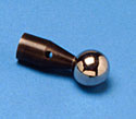
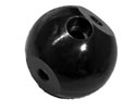
We offer a family of off the shelf parts that can be purchased individually and assembled into C.M.M. evaluation artifacts (Pretzel). These individual pieces can be built up into a C.M.M. evaluation pretzel and later the same pieces can be reassembled into a totally different design to check an entirely different machine function. At the heart of these component parts are the individual pieces of the adjustable Ball Bar family. The Adjustable Ball Bar ends, come in two different standard sphere diameters.
- Part number ABB-PB-100 is equipped with one inch diameter very high quality, Grade 5 spheres. These spheres are perfectly round within five microinches ( 0.000127 mm ) maximum and has a 0.7 microinch ( 0.0000178 mm ) RA surface texture maximum.
- Part number ABB-PB-75 is equipped with a three quarter inch 0.750” ( 19.05 mm ) diameter very high quality Grade 5 spheres. These spheres are perfectly round within five micro inches (0.000127mm) maximum and have a 0.7 micro inch RA ( 0.0000178 mm ) maximum surface texture.
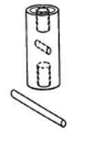
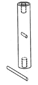
We offer three short Ball Bar extensions that find application in the construction of C.M.M. pretzels.
- Part number ABB-50 is a 50 mm ( 1.9685” ) long extension. They are supplied with 5/16” diameter N.C. mounting screws.
- Part number ABB-100 is a 100 mm ( 3.9370” ) long extension. They are supplied with 5/16” diameter N.C. mounting screws.
- Part number ABB-200 is a 200 mm ( 7.8740” ) long extension. They are supplied with 5/16” diameter N.C. mounting screws.
- Part number ABB-600 is a 600 mm ( 23.62” ) long. They are supplied with 5/16” diameter N.C. mounting screws.
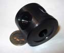
We offer an exceptionally versatile four place turret Part number FPT-150, that is excellent for mounting adjustable ball bar ends. This turret has four, five sixteenths inch ( 5/16”, 0.3125”) [7.9375mm] diameter national coarse female threads that match the internal threads in the adjustable Ball Bar ends. This turret will hold a variety of four Adjustable Ball Bar ends simultaneously.
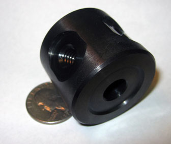
We offer two different lengths of heavy duty risers, that are one and one quarter inch ( 6.35 mm ) diameter, with an M10x1.5 thread that is one half inch 1/2” ( 12.7 mm ) deep in each end.
- The three inch 3” ( 76.2 mm ) tall, version of the risers is our part number P-EP-3.
- The six inch 6” ( 152.4 mm ) tall, version of the risers is our part number P-EP-6.
We offer a two by two block that is 2.0 inches square, with 4 threaded holes that are M10-1.5. It has a tie down hole in the center of the top, that is 0.4 inch (10 mm) diameter. It will accept an M10 or a 3/8 inch diameter tie down cap screw.
Another handy accessory is the Knuckle, Part number KN-1. This device facilitates mounting artifacts at 45 degrees and or at 90 degrees to the base.
It has two M10x1.5 female threads that are one half inch 1/2" ( 12.7 mm ) deep and one counter bored 10 mm ( 0.40 inch ) hold down hole, through the center, that is counter bored to take a cap screw.
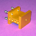
We offer a Gage Block Clamp that will hold two rectangular or square gage blocks. This is our Part number GC-2. It has two five sixteenths of an inch, national coarse female, mounting holes, ( 5/16”, 0.3125”, 7.9375 mm ) that are one half inch 1/2” ( 12.7 mm ) deep.
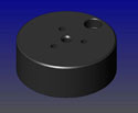
There is a very rugged 4.0 inch diameter puck or platform available that is Part number PLT-4. This provides a very stable mounting base for any artifact that you build. It is built, to work with M10 or 3/8 inch diameter tie down screws.
You can assemble any length Ball Bar, for mounting on the Two by Two block, by attaching two of the Ball Bar ends to the desired length, adjustable Ball Bar shaft. This Ball Bar can be attached, to the Two by Two block, with the standard Ball Bar Clamp- Part number FS-1BB which will connect to the Two by Two Block with an M10-1.5 shoulder Bolt.
An outstanding design, for a fixed artifact, can be assembled from two Ball Bars that are in turn assembled from four Ball Bar ends Part number ABB-PB-100, or ABB-PB-75 and two adjustable Ball Bar shafts of the desired length.
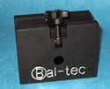
These two Ball Bars are clamped on opposite sides of a two by two block, with two of our standard Ball Bar Clamps- Part Number FS-1BB.
This combination is typically elevated on a six inch or taller heavy duty riser. The two Ball Bars are inclined at about a 45 degree angle to the table, each in the opposite directions.
An Artifact Assembly Kit for C.M.M.S — A Kit to Assemble C.M.M. Pretzels
We offer an artifact assembly kit, our Part Number AAK-23, that will provide all of the component parts, to assemble a wide variety of C.M.M. evaluation hardware, usually referred to as “Pretzels”.
This Full kit consists of:
- Four pieces of Adjustable Ball Bar Ends which are Part Number # ABB-PB-100. These use very precise Grade 5 one inch ( 1.00”, 25.4 mm ) diameter master balls, that are spherical within five microinches (.000127mm) and have a 0.7 (.000017mm) microinch RA surface texture. They are supplied with five sixteenths national coarse mounting screws.
- Two pieces, of Adjustable Ball Bar extensions, which are Part Number# ABB-50. These are 50 mm (1.968”) long. They are supplied with 5/16” diameter N.C. mounting screws.
- Two pieces of Ball Bar extensions, which are Part Number # ABB-100. These are 100 mm ( 3.937”) long. They are supplied with 5/16” diameter N.C. mounting screws.
- Two pieces, of Adjustable Ball Bar extension which are Part number ABB-200. These are 200 mm ( 7.874 inches long. They are supplied with 5/16” diameter N.C. mounting screws.
- Two pieces of Adjustable Ball Bar extensions, which are Part Number# ABB-600. These are 600 mm ( 23.62” ) long. They are supplied with 5/16” diameter N.C. mounting screws.
- One four place turret Part Number# FPT-150, with an M10-1.5 or 3/8 of an inch tie down cap screw. It has four five sixteenths of an inch ( 5/16", 7.937 mm ) national coarse mounting holes.
- One, two by two inch Block Part Number # BLK-2 which comes with an M10-1.5 diameter tie down cap screw. There is a M10-1.5 threaded mounting hole in each of the four vertical faces.
- One three inch tall heavy duty extension, which is Part Number P-EP-3. This has an M10-1.5 threaded mounting hole on each end.
- One six inch tall heavy duty extension, which is Part Number P-EP-6. This has an M10-1.5 threaded mounting hole on each end.
- One Heavy Duty four inch 4” (101.6mm) diameter mounting base or platform, Part number PLT-4 with M10-1.5 tie down cap screws.
- One knuckle, Part Number # KN-1 with an M10-1.5, tie down cap screw. This device will hold an artifact at 45 degrees and or one at 90 degrees, through two M10.1.5 threaded holes, that are one half inch (0.5”) [12.7mm] deep.
- Two pieces of the Ball Bar Clamps Part Number # FS-1BB, with the clamping fasteners. These are typically used to hold longer Ball Bars on the Two by Two Block.
- One piece of our Gage Block Clamp, that will hold two rectangular or square gage blocks. This is our Part Number GC-2. It has two five sixteenths of an inch ( 5/16", 0.3125", 7.937 mm ) national coarse female mounting holes.
