Bal-tec™ Home Kinematic Components Catalog 105-B
Kinematics Catalog #105-B
Free Viewer
Down load free SolidWorks eDrawing ™ viewer
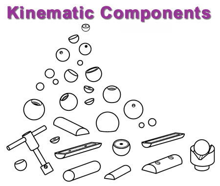
Kinematic Components—Graphical Summary Page
Click on component for more information





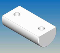


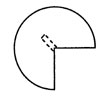

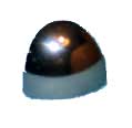
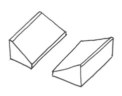
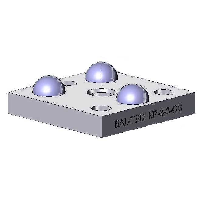

Introduction to Standardized Tooling Instrument and Kinematic Components For precise location in gaging, tooling and scientific instruments
The fundamental kinematic mount is a specialized method of coupling two elements in a mechanical system. One element is usually fixed to the frame of the apparatus, and the other is portable or movable. In a well designed mount, the portable element can be removed and replaced or indexed with nanometric repeatability. The concept of the kinematic mount is to eliminate any or all of the six degrees of freedom between the two elements of the system without using any strenuous clamping or over constraint. These degrees of freedom are usually defined as the three straight axis-"X" axis, "Y" axis,"Z" axis and the rotational axis of pitch, yaw and roll. A large number of variations on the fundamental Kinematic design have been developed. The "classical" design uses three spherical points of contact (balls) that are usually incorporated into one of these elements.
The second element incorporates a vee groove, a conical cup and a plane surface. Some of the factors that limit the ultimate accuracy of a kinematic system are the extreme difficulties of generating high quality conical cups and vee grooves. These problems can be solved using our kinematic components. By substituting two of our high-quality cylinders for the vee grooves and three of our high-quality spheres for the cone, you can achieve orders of magnitude improvement in repeatability. A careful choice of material is required in order to avoid the problem of fretting. Fretting may occur due to the high elastic loads caused by the small contact areas characteristic of most kinematic designs. We have developed our product line around an excellent fret-resistant material. It is a through-hardened, high-chrome, high-carbon stainless steel.
Another excellent choice of material is tungsten carbide. It is very fret-resistant and has an extremely high rigidity (i.e., Young's Modulus of Elasticity). Since it is much more expensive, it is not as widely used. Because there is little or no movement between the elements of a kinematic mount, the same material can be used for all components without the usual problems of wear and galling. Although we manufacture an extensive and expanding line of standard kinematic components, we will also custom-manufacture unique high quality components to your specifications. These may be made of materials with special heat or corrosive-resistant properties, or with different magnetic or electrical characteristics. They may be tailored to fit ideally into your products. These include prismatic Vee-Blocks with optical-quality metal surfaces, Kelvin trihedral cups with optical-quality metal facets and cathedral or Gothic arch-vees with optical quality radii.
Complete Ball as a Kinematic Component

| Downloads | ||
|---|---|---|
| Solidworks | IGES | |
| N/A | ||
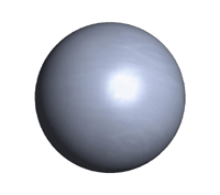
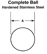
A complete ball should be used whenever possible. It is the lowest cost and highest-quality product. In many applications, they can be staked or press-fit into place. In low stress applications, the ball can be glued into the assembly. When gluing a ball into an assembly, the cleanliness of the surfaces is of the greatest importance.
| Part No. | A-Diameter ±.0001" | Sphericity |
|---|---|---|
| 187-B | .1875" 4.763 mm |
.000010" .000254 mm |
| 250-B | .250" 6.35 mm |
.000010" .000254 mm |
| 312-B | .3125" 7.9375 mm |
.000010" 000254 mm |
| 375-B | .3750" 9.525 mm |
.000010" .000254 mm |
| 500-B | .500" 12.700 mm |
.000010" .000254 mm |
| 625-B | .625" 15.87 mm |
.000010" .000254 mm |
| 750-B | .750" 19.05 mm |
.000010" .000254 mm |
| 100-B | 1.00" 25.4 mm |
.000010" .000254 mm |
Ball Pricing
| Part # | Price | Purchase |
|---|---|---|
| 187-B | $7.50 | |
| 250-B | $7.50 | |
| 312-B | $7.50 | |
| 375-B | $7.50 | |
| 500-B | $7.50 | |
| 625-B | $9.22 | |
| 750-B | $10.95 | |
| 100-B | $13.81 | |
Truncated Ball
| Downloads | ||
|---|---|---|
| Solidworks | IGES | |
| N/A | ||
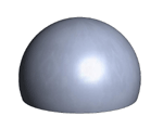
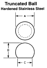
The truncated ball is the least expensive of our modified balls. The reduced profile height, the added stability of the flat base, and the higher load carrying capacity are its main selling points. It is often used in non-kinematic applications such as self-aligning clamps, support feet and location points.
| Part No. | A-Diameter ±.0001" | B-Height ±.002" | C-Diameter Reference |
|---|---|---|---|
| 187-TB | .1875" 4.763 mm |
.125" 3.175 mm |
.1767" 4.488 mm |
| 250-TB | .250" 6.35 mm |
.167" 4.242 mm |
.235" 5.97 mm |
| 312-TB | .3125" 7.9375 mm |
.208" 5.283 mm |
.294" 7.468 mm |
| 375-TB | .3750" 9.525 mm |
.250" 6.35 mm |
.353" 8.966 mm |
| 500-TB | .500" 12.700 mm |
.334" 8.484 mm |
.471" 11.963 mm |
| 625-TB | .625" 15.875 mm |
||
| 750-TB | .750" 19.05 mm |
.500" 12.70 mm |
.707" 17.958 mm |
| 100-TB | 1.00" 25.4 mm |
.750" 19.05 mm |
.866" 21.1 mm |
Truncated Ball Pricing
| Part # | Price | Purchase |
|---|---|---|
| 187-TB | $12.87 | |
| 250-TB | $13.53 | |
| 312-TB | $13.75 | |
| 375-TB | $14.30 | |
| 500-TB | $14.85 | |
| 625-TB | $18.32 | |
| 750-TB | $18.32 | |
| 100-TB | $23.38 | |
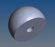
Truncated Ball with Blind Hole
Hardened Stainless Steel, 58 HRC.
| Downloads | ||
|---|---|---|
| Solidworks | IGES | |
| N/A | ||
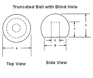
The truncated ball with a blind hole is a low-cost modified ball with high mounting strength. This version is usually pinned and glued to hold it in position. This design is often employed in production applications where large numbers of kinematic components require maximum economy. The reduced profile height, the added stability of the flat base and the higher load-carrying capacity are all good selling points for this design.
| Part No. | A-Diameter ±.0001" | B-Diameter Reference | C-Height ±.002" | E-Diameter | F-Depth |
|---|---|---|---|---|---|
| 187-TB-BH | 0.1875" 4.763 mm |
0.1767" 4.488 mm |
0.125" 3.175 mm |
0.0625" 1.59 mm |
0.0625" 1.59 mm |
| 250-TB-BH | 0.250" 6.35 mm |
0.235" 5.97 mm |
0.167" 4.242 mm |
0.0625" 1.59 mm |
0.0625" 1.59 mm |
| 312-TB-BH | 0.3125" 7.9375 mm |
0.294" 7.468 mm |
0.208" 5.283 mm |
0.09375" 2.38 mm |
0.09375" 2.38 mm |
| 375-TB-BH | 0.3750" 9.525 mm |
0.353" 8.966 mm |
0.250" 6.35 mm |
0.125" 3.18 mm |
0.125" 3.18 mm |
| 500-TB-BH | 0.500" 12.700 mm |
0.471" 11.963 mm |
0.334" 8.484 mm |
0.15625" 3.97 mm |
0.15625" 3.97 mm |
| 625-TB-BH | 0.625" 15.875 mm |
||||
| 750-TB-BH | 0.750" 19.05 mm |
0.707" 17.958 mm |
0.500" 12.70 mm |
0.15625" 3.97 mm |
0.15625" 3.97 mm |
| 100-TB-BH | 1.000" 25.4 mm |
0.866" 21.996 mm |
0.750" 19.05 mm |
0.1875" 4.76 mm |
0.1875" 4.76 mm |
Truncated Ball with Blind Hole Pricing
| Part # | Price | Purchase |
|---|---|---|
| 187-TB-BH | $19.47 | |
| 250-TB-BH | $19.58 | |
| 312-TB-BH | $20.13 | |
| 375-TB-BH | $31.35 | |
| 500-TB-BH | $23.87 | |
| 625-TB-BH | $23.49 | |
| 750-TB-BH | $28.60 | |
| 100-TB-BH | $30.47 | |
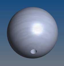
Ball with Concentric Blind Hole
Made from Hardened Stainless Steel
| Downloads | ||
|---|---|---|
| Solidworks | IGES | |
| N/A | ||
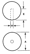
These modified balls make good elements for kinematic systems, where this simple design can be applied. This general purpose component is widely used by the gage industry. The .500", and .750" balls are also available in instrument quality with 5 microinch sphericity and ultra high quality with 2.5 microinch sphericity. They are used to construct ball bars, ball trees, reference spheres, etc. Tungsten Carbide is available on special order.
| Part No. | A-Diameter ±.0001" | E-Diameter ±.002" | F-Depth Reference |
|---|---|---|---|
| 187-BBH | .1875" 4.763 mm |
.062 1.587 mm |
.100 2.54 mm |
| 250-BBH | .250" 6.35 mm |
.0625" 1.587 mm |
.125" 3.175 mm |
| 312-BBH | .3125" 7.9375 mm |
.09375" 2.381 mm |
.125" 3.175 mm |
| 375-BBH | .3750" 9.525 mm |
.09375" 2.83 mm |
.125" 3.175 mm |
| 500-BBH | .500" 12.700 mm |
.125" 3.175 mm |
.250" 6.35 mm |
| 625-BBH | .625" 15.875 mm |
||
| 750-BBH | .750" 19.05 mm |
.125" 3.175 mm |
.300" 7.620 mm |
| 100-BBH | 1.00" 25.4 mm |
.125" 3.175 mm |
.300" 7.620 mm |
Ball with Concentric Blind Hole Pricing
Truncated and Recessed Ball
Hardened Stainless Steel with an Extended Glue Line
| Downloads | ||
|---|---|---|
| Solidworks | IGES | |
| N/A | ||
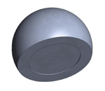
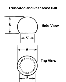
The truncated and recessed ball is an inexpensive modified ball form. The annular ring resulting from the recess forms an extremely stable mounting surface. The very rough Electrical Discharge Machined surface of the recess is excellent for gluing. This form has a much lower profile than a complete ball. The design has a .005" deep recess on its flat surface that is made very rough by Electrical Discharge Machining. This rough surface is used in applications where the ball is glued in place.
| Part No. | A-Diameter ±.0001" | B-Height ±.002" | C-Diameter Reference | D-Diameter Reference |
|---|---|---|---|---|
| 187-TBR | .1875 4.763 mm |
.125 3.175 mm |
.1767 4.488 mm |
0 |
| 250-TBR | .250" 6.35 mm |
.167" 4.242 mm |
.235" 5.97 mm |
.175" 4.44 mm |
| 312-TBR | .3125" 7.9375 mm |
.208" 5.283 mm |
.294" 7.468 mm |
.200" 5.08 mm |
| 375-TBR | .3750" 9.525 mm |
.250" 6.35 mm |
.350" 8.966 mm |
.250" 6.35 mm |
| 500-TBR | .500" 12.700 mm |
.334" 8.484 mm |
.471" 11.963 mm |
.325" 8.25 mm |
| 625-TBR | .625" 15.875 mm |
|||
| 750-TBR | .750" 19.05 mm |
.500" 12.70 mm |
.707" 17.958 mm |
.500" 12.70 mm |
| 100-TBR | 1.00" 25.4 mm |
.750" 19.05 mm |
.866" 21.1 mm |
.666" 17 mm |
Truncated and Recessed Ball Pricing
| Part # | Price | Purchase |
|---|---|---|
| 187-TBR | $17.38 | |
| 250-TBR | $17.38 | |
| 312-TBR | $17.60 | |
| 375-TBR | $18.15 | |
| 500-TBR | $19.80 | |
| 625-TBR | $23.27 | |
| 750-TBR | $22.17 | |
| 100-TBR | $26.13 | |
Truncated and Threaded Ball
Made From Hardened Stainless Steel with an Extended Glue Line and Tapped Hole
| Downloads | ||
|---|---|---|
| Solidworks | IGES | |
| N/A | ||
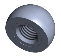
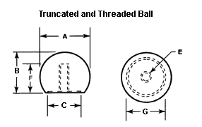
Because the ball is held from behind with a machine screw, there is no interruption of the spherical surface. This provides a smooth, clean working surface. The truncated and threaded ball is our most widely used kinematic component. This ball is held in place by a threaded fastener. It has a .005" deep recess on the flat surface that is made very rough by Electrical Discharge Machining (EDM). When maximum reliability is required, glue may be applied to this rough surface to form a permanent bond between this component, the machine screw, and the mounting surface.
The annular ring resulting from the recess forms an extremely stable mounting surface. Three of these balls provide a very high quality substitute for a conical cup or trihedral clamp. This design has a much lower profile height than a complete ball. These balls are an excellent choice for the three spherical contact points in the kinematic system.
| Part No. | A-Diameter ±.0001" | B-Height ±.002" | C-Diameter Reference | E-Thread | F-Depth Minimum | G-Diameter Reference |
|---|---|---|---|---|---|---|
| 250-TBR-T | .250" 6.35 mm |
.167" 4.242 mm |
.236" 5.97 mm |
4-40 | .116" 28.35 mm |
.175" 4.445 mm |
| 312-TBR-T | .3125" 7.9375 mm |
.208" 5.283 mm |
.295" 7.468 mm |
6-32 |
.150" 3.81 mm |
.200" 5.08 mm |
| 375-TBR-T | .3750" 9.525 mm |
.250" 6.35 mm |
.354" 8.966 mm |
10-32 |
.200" 5.08 mm |
.250" 6.35 mm |
| 500-TBR-T | .500" 12.700 mm |
.334" 8.484 mm |
.471" 11.963 mm |
1/4-20 |
.250" 6.35 mm |
.325" 8.25 mm |
| 625-TBR-T | .625" 12.700 mm |
.417" 10.59 mm |
.589" 14.96 mm |
1/4-20 | .250" 6.35mm |
|
| 750-TBR-T | .750" 19.05 mm |
.500" 12.70 mm |
.707" 17.958 mm |
1/4-20 |
.250" 6.35 mm |
.500" 12.70 mm |
| 100-TBR-T | 1.00" 25.4 mm |
.750" 19.05 mm |
.866" 21.1 mm |
1/4-20 |
.250" 6.35 mm |
.666" 17 mm |
| 200-TBR-T | 2.00" 50.8 mm |
1.500" 38.1 mm |
1/4-20 | .250" 6.35mm |
Truncated and Threaded Ball Pricing
| Part # | Price | Purchase |
|---|---|---|
| 250-TBR-T | $36.30 | |
| 312-TBR-T | $36.30 | |
| 375-TBR-T | $35.20 | |
| 500-TBR-T | $35.20 | |
| 625-TBR-T | $35.20 | |
| 750-TBR-T | $35.20 | |
| 100-TBR-T | $38.50 | |
| 200-TBR-T | $212.00 | |
Truncated Ball with Counter Bored Hole
Made from Hardened Stainless Steel with an Extended Glue Line
| Downloads | ||
|---|---|---|
| Solidworks | IGES | |
| N/A | ||
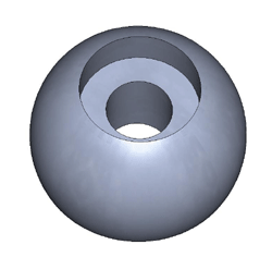
The truncated and counterbored ball is the second most widely used kinematic component. It is used where the component must be held in place from the front side. Three of these balls provide a very high-quality substitute for a conical cup or a trihedral clamp. These balls are a good choice for the three spherical contact points in the kinematic system when the ball can only be held in place from the front side. This component has a much lower profile than a complete ball.
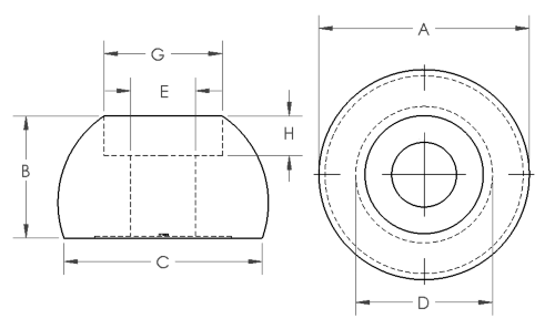
This component has a .005" deep recess on the flat surface that is made very rough by Electrical Discharge Machining. When maximum reliability is required, glue may be applied to this rough surface to form a permanent bond between this component, the machine screw, and the mounting surface. This component is machined for use with a standard socket head cap screw. The "A" diameter is the outside diameter of the ball. The "B" height is the height of the ball, before the counter bored section of the ball was machined. The "C" diameter is the diameter of the landing area on the bottom of the ball. The "E" diameter is the diameter of the through hole. The "F" diameter is the diameter of the counter bored hole. The "G" depth is the depth of the counter bored hole. The "H" diameter is the diameter of the recessed area on the bottom of the ball.
Truncated Ball with Counterbore Specifications
| Part No. | A-Dia. ±.0001" Ball |
B-Height ±.002" Ball |
C-Dia. Ref. | Screw Size | E-Dia. Ref. Thru hole |
F-Dia. Ref. Counter bored |
G-Depth Ref. | H-Dia. Ref. |
|---|---|---|---|---|---|---|---|---|
| 250-TBR-CB | .250" 6.35 mm |
.167" 4.242 mm |
.175" 4.45 mm |
.0920" 2.337 mm |
.145" 3.683 mm |
.092" 2.337 mm |
||
| 312-TBR-CB | .3125" 7.9375 mm |
.208" 5.283 mm |
.294" 7.468 mm |
#4 |
.125" 3.175 mm |
.218" 5.537 mm |
.125" 3.175 mm |
.228" 5.791 mm |
| 375-TBR-CB | .3750" 9.525 mm |
.250" 6.35 mm |
.353" 6.35 mm |
#4 |
.125" 3.175 mm |
.218" 5.537 mm |
.125" 3.175 mm |
.242" 8.966 mm |
| 500-TBR-CB | .500" 12.700 mm |
.334" 8.484 mm |
.471" 11.963 mm |
#6 |
.154" 3.91 mm |
.281" 7.137 mm |
.138" 3.505 mm |
.325" 8.25 mm |
| 625-TBR-CB | .625" 15.875 mm |
.385" 9.779 mm |
.589" 14.9606 mm |
.170" 4.318 mm |
.275" 6.985 mm |
.175" 4.445 mm |
||
| 750-TBR-CB | .750" 19.05 mm |
.500" 12.70 mm |
.707" 17.958 mm |
#10 |
.206" 5.232 mm |
.375" 9.52 mm |
.190" 4.826 mm |
.500" 12.70 mm |
| 100-TBR-CB | 1.00" 25.4 mm |
.750" 19.05 mm |
.866" 21.1 mm |
1/4" |
.250" 6.35 mm |
.375" 9.52 mm |
.250" 6.35 mm |
.666" 17 mm |
| 200-TBR-CB | 2.00" 50.8 mm |
1.332" 33.83 mm |
custom | .380" 9.65 mm |
custom | .430" 10.92 mm |
1,375" 34.93 mm |
Truncated Ball with Counterbore Pricing
| Part # | Price | Purchase |
|---|---|---|
| 250-TBR-CB | $38.50 | |
| 312-TBR-CB | $38.50 | |
| 375-TBR-CB | $38.50 | |
| 500-TBR-CB | $38.50 | |
| 625-TBR-CB | $38.50 | |
| 750-TBR-CB | $42.90 | |
| $0.00 | |
Full Ball with Counterbored Hole
Made from Hardened Stainless Steel. This component is machined for use with a standard socket head cap screw.
| Downloads | ||
|---|---|---|
| Solidworks | IGES | |
| N/A | ||
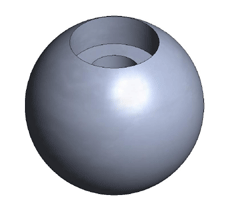
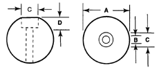
This component is less expensive than the truncated ball with a counterbored hole. It is very effective when a reduced profile is not important. A socket head cap screw is usually used to pull
| Part No. | A-Diameter ±.0001" | Screw Size | B-Diameter Reference | C-Diameter ±.002" | D-Depth Reference |
|---|---|---|---|---|---|
| 250-B-CB | .250 6.35 mm |
.235 5.97 mm |
|||
| 312-B-CB | .3125" 7.9375 mm |
#4 |
.125" 3.175 mm |
.218" 5.537 mm |
.125" 3.175 mm |
| 375-B-CB | .3750" 9.525 mm |
#4 |
.125" 3.175 mm |
.218" 5.537 mm |
.125" 3.175 mm |
| 500-B-CB | .500" 12.700 mm |
#6 |
.154" 3.91 mm |
.281" 7.137 mm |
.138" 3.505 mm |
| 625-B-CB | .625" 15.875 mm |
||||
| 750-B-CB | .750" 19.05 mm |
#10 |
.206" 5.232 mm |
.375" 9.52 mm |
.190" 4.826 mm |
| 100-B-CB | 1.00" 25.4 mm |
1/4" |
.250" 6.35 mm |
.375" 9.52 mm |
.250" 6.35 mm |
Full Ball with Counterbored Hole Pricing
Threaded Ball
Made from Hardened Stainless Steel with a Tapped Hole
| Downloads | ||
|---|---|---|
| Solidworks | IGES | |
| N/A | ||
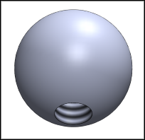
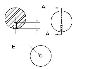
A very sound approach for rigidly holding the spherical components on a Kinematic Platform is to use drilled and threaded balls. The drilled and threaded balls have gained great popularity of late. This surge in popularity is based on the results of some recent kinematic research that indicates that a ball glued into a mating spherical cup is very sturdy, and may even be the best way to mount a ball. The ball is held rigidly in position by a thin glue joint. This design has high shear-resistance, as the ball is buried in the recessed spherical-cavity. It can not torque due to the threaded shank of the holding screw. In addition, it is insensitive to hygroscopy of the glue because there is almost no exposure of the glue line to the atmosphere.
This ball is held in place by a threaded fastener. Because the ball is held from behind with a machine screw, there is no interruption of the spherical surface. This provides a smooth, clean working surface. The Lotus Wrench shown in the Kinematic Components Catalog #105B is an excellent tool for installing these balls from the front. Three of these balls provide a very high quality substitute for a conical cup or trihedral clamp. These balls are an excellent choice for the three spherical contact points in the kinematic system.
Standard drilled and threaded balls are offered in micro-grain 440C stainless steel that is hardened to 58 HRC minimum, or in extremely stiff tungsten carbide (TC) with a Young's Modulus of Elasticity of 98,000,000 PSI and a very high hardness of 91 HRA. TC is the hardest, most rigid material commonly available.
Threaded Ball Specifications
| Part No. | A-Diameter ± 0.0001" | E-Thread | F-Depth Minimum |
|---|---|---|---|
| 250-B-T | 0.25" 6.35 mm |
4-40 | 0.150" 3.81 mm |
| 312-B-T | 0.3125" 7.9375 mm |
6-32 | 0.150" 3.81 mm |
| 375-B-T | 0.3750" 9.525 mm |
10-32 | 0.200" 5.08 mm |
| 500-B-T | 0.500" 12.700 mm |
1/4-20 | 0.250" 6.35 mm |
| 625-B-T | 0.625" 12.700 mm |
1/4-20 | 0.250" 6.35 mm |
| 750-B-T | 0.750" 19.05 mm |
1/4-20 | 0.250" 6.35 mm |
| 100-B-T | 1.000" 25.4 mm |
1/4-20 | 0.250" 6.35 mm |
Threaded Ball Prices
Lotus Wrench
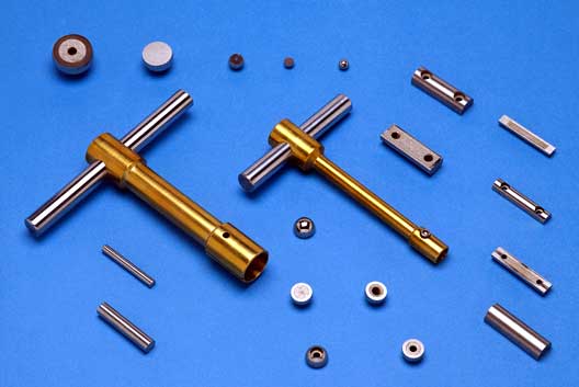
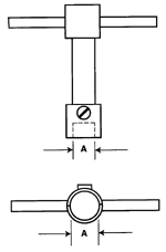
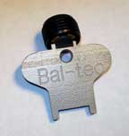
The Lotus Wrench is a tool designed exclusively for installing truncated and threaded balls. The ball is simply placed on a flat surface, and the open wrench is placed over it. The screw in the side of the wrench is tightened, clamping the ball solidly. The ball is screwed into position. When the side-screw is loosened, the wrench opens and is removed. The wrench is made of non-marring brass to prevent degradation to the quality of the ball.
Complete Cylinder
Hardened Stainless Steel
| Downloads | ||
|---|---|---|
| Solidworks | IGES | |
| N/A | ||
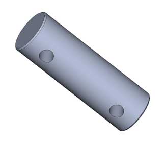
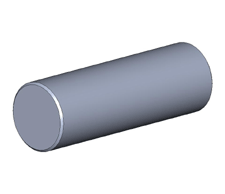
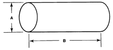
The complete cylinder is a low cost, high quality component widely used in kinematic applications. Two parallel mounted cylinders form a very high quality substitute for the hard-to-manufacture vee groove. These hardened and dimensionally stabilized stainless steel cylinders are precision ground and machine lapped to provide excellent cylindricity with close dimensional tolerance. The highly uniform low microinch surface texture generated by the machine lapping leads to low hysteresis and excellent repeatability. These complete cylinders can be press fit, shrink fit or glued into mating holes. They can also be clamped in place by a number of different methods. The surface finish is 1 microinch Ra maximum (.0000254 mm). The cylindricity of all cylinders is .000020" (.000508 mm).
| Part No. | A-Diameter, ±.0001" | B-Length, Reference |
|---|---|---|
| 187-C | .1875", 4.763 mm | 1.5", 38.100 mm |
| 250-C | .250", 6.35 mm | 1.5", 38.100 mm |
| 312-C | .3125", 7.9375 mm | 1.5", 38.100 mm |
| 375-C | .3750", 9.525 mm | 1.5", 38.100 mm |
| 500-C | .500'', 12.700 mm | 1.5", 38.100 mm |
| 625-C | .625'', 15.875 mm | 1.5", 38.100 mm |
| 750-C | .750", 19.05 mm | 1.5", 38.100 mm |
| 100-C | 1.00", 25.4 mm | 1.5", 38.100 mm |
Truncated Cylinder with Counterbored Holes
Made from Hardened Stainless Steel with an Extended Glue Line
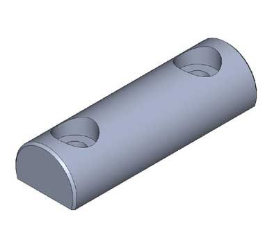
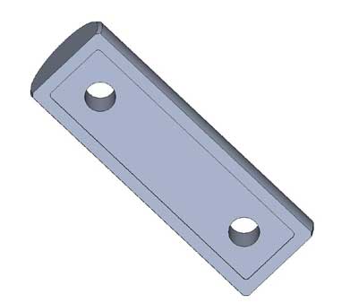
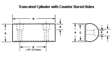
The truncated cylinder with counterbored holes is our second most popular cylindrical component. It is used when the components must be held in place from the front side. These hardened and dimensionally stabilized stainless steel cylinders are precision ground and machine lapped to provide excellent cylindricity with close dimensional tolerance. The highly uniform low microinch surface texture generated by the machine lapping leads to low hysteresis and excellent repeatability. The land left around the edge of the flat due to the recess forms an extremely stable mounting surface. Two parallel mounted cylinders form a very high quality substitute for the hard-to-manufacture vee groove.
| Downloads | ||
|---|---|---|
| Solidworks | IGES | |
| N/A | ||
This design has a 0.005" deep recess on its flat surface that is made very rough by Electrical Discharge Machining ( EDM ). When maximum reliability is required, glue may be applied to this rough surface to form a permanent bond between this component, the machine screw, and the mounting surface. This component is machined for use with a standard socket head cap screw.
Truncated Cylinder with Counter Bored Holes Specifications
The "H" dimension is from center line to center line. It is 1.00" (25.4 mm) on all parts.
| Part No. | A-Diameter ±.0001" | B-Length Reference | C-Width Reference | D-Height ±.002" | Screw Size | E-Dial Reference | F-Dia. Reference | G-Depth Reference |
|---|---|---|---|---|---|---|---|---|
| 250-TCR-CB | .250" 6.35 mm |
1.5" 38.100 mm |
.235" 5.97 mm |
.167" 4.242 mm |
#2 | .094" 2.288 mm |
.187" 4.750 mm |
.086" 2.184 mm |
| 312-TCR-CB | .3125" 7.9375 mm |
1.5" 38.100 mm |
.294" 7.468 mm |
.208" 5.283 mm |
#4 | .125" 3.175 mm |
.218" 5.537 mm |
.125" 3.175 mm |
| 375-TCR-CB | .3750" 9.525 mm |
1.5" 38.100 mm |
.353" 8.966 mm |
.250" 6.35 mm |
#4 | .125" 3.175 mm |
.218" 5.537 mm |
.125" 3.175 mm |
| 500-TCR-CB | .500" 12.700 mm |
1.5" 38.100 mm |
.471" 11.963 mm |
.334" 8.484 mm |
#6 | .154" 3.91 mm |
.281" 7.137 mm |
.138" 3.505 mm |
| 625-TCR-CB | .625" 15.875 mm |
1.5" 38.100 mm |
||||||
| 750-TCR-CB | .750" 19.05 mm |
1.5" 38.100 mm |
.707" 17.958 mm |
.500" 12.700 mm |
#10 | .206" 5.323 mm |
.375" 9.52 mm |
1.90" 4.826 mm |
| 100-TCR-CB | 1.00" 25.4 mm |
1.5" 38.100 mm |
.866" 21.1 mm |
.750" 19.05 mm |
1/4" | .206" 6.35 mm |
.375" 9.52 mm |
0.250" 6.35 mm |
Truncated Cylinder with Counterbored Holes Pricing
| Part # | Price | Purchase |
|---|---|---|
| 250-TCR-CB | $41.69 | |
| 312-TCR-CB | $41.69 | |
| 375-TCR-CB | $42.35 | |
| 500-TCR-CB | $52.69 | |
| 625-TCR-CB | $53.24 | |
| 750-TCR-CB | $53.79 | |
| 100-TCR-CB | $69.96 | |
Cylinder with Two Concentric Blind Holes
Made with Hardened Stainless Steel

| Downloads | ||
|---|---|---|
| Solidworks | IGES | |
| N/A | ||
They make good elements for kinematic systems, where this simple design can be applied. This general purpose component is widely used by the gage industry. The .500", and .750" Cylinders are also available Tungsten Carbide is available on special order.
Cylinder with Two Concentric Blind Holes Specifications
| Part No. | A-Diameter ±.0001" | H-Diameter ±.002" | E-Depth Reference | Length |
|---|---|---|---|---|
| 187-CBH | .1875" 4.763 mm |
.062 1.587 mm |
.100 2.54 mm |
1.5" 38.1 mm |
| 250-CBH | .250" 6.35 mm |
.0625" 1.587 mm |
.125" 3.175 mm |
1.5" 38.1 mm |
| 312-CBH | .3125" 7.9375 mm |
.09375" 2.381 mm |
.125" 3.175 mm |
1.5" 38.1 mm |
| 375-CBH | .3750" 9.525 mm |
.09375" 2.83 mm |
.125" 3.175 mm |
1.5" 38.1 mm |
| 500-CBH | .500" 12.700 mm |
.125" 3.175 mm |
.250" 6.35 mm |
1.5" 38.1 mm |
| 625-CBH | .625" 15.875 mm |
.125" 3.175 mm |
||
| 750-CBH | .750" 19.05 mm |
.125" 3.175 mm |
.300" 7.620 mm |
1.5" 38.1 mm |
| 100-CBH | 1.00" 25.4 mm |
.125" 3.175 mm |
.300" 7.620 mm |
1.5" 38.1 mm |
Cylinder with Two Concentric Blind Holes Pricing
| Part # | Price | Purchase |
|---|---|---|
| 187-CBH | $17.82 | |
| 250-CBH | $17.88 | |
| 312-CBH | $18.10 | |
| 375-CBH | $18.10 | |
| 500-CBH | $19.36 | |
| 625-CBH | $26.02 | |
| 750-CBH | $32.67 | |
| 100-CBH | $36.96 | |
Threaded Cylinder
Made from Hardened Stainless Steel with Tapped Holes
| Downloads | ||
|---|---|---|
| Solidworks | IGES | |
| N/A | ||
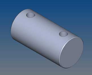
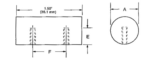
Because the cylinder is held from behind with machine screws, there is no interruption of the cylindrical surface. This provides a smooth, clean working surface. These hardened and dimensionally stable stainless steel cylinders are precision ground and machine lapped to provide excellent cylindricity with close dimensional tolerance.
Kinematic Threaded Cylinders
| Part No. | A-Diameter ±.0001" | Screw Size | E-Depth Reference | F-Center Line |
|---|---|---|---|---|
| 250-C-T | .250" | 6-32 | .125" | 1.00" |
| 6.35 mm | 3.175 mm | 25.4 mm | ||
| 312-C-T | .3125" | 6-32 | .154" | 1.00" |
| 7.9375 mm | 3.91 mm | 2.54 mm | ||
| 375-C-T | .3750" | 10-32 | .200" | 1.00" |
| 9.525 mm | 5.08 mm | 25.4 mm | ||
| 500-C-T | .500" | 1/4"-20 | .250" | 1.00" |
| 12.70 mm | 6.35 mm | 25.4 mm | ||
| 625-C-T | .625" | 1/4"-20 | .250" | 1.00" |
| 15.875 mm | 6.35 mm | 25.4 mm | ||
| 750-C-T | .750" | 1/4"-20 | .250" | 1.00" |
| 19.05 mm | 6.35 mm | 25.4 mm | ||
| 100-C-T | 1.00" | 1/4"-20 | .250" | 1.00" |
| 25.40 mm | 6.35 mm | 25.4 mm |
The highly regular, low micro inch surface texture generated by the machine lapping leads to low hysteresis and excellent repeatability. Two parallel mounted cylinders, held in place by machine screws form a very high quality substitute for the hard-to-manufacture vee groove.
| Part # | Price | Purchase |
|---|---|---|
| 250-C-T | $33.77 | |
| 312-C-T | $33.77 | |
| 375-C-T | $34.60 | |
| 500-C-T | $36.96 | |
| 625-C-T | $37.88 | |
| 750-C-T | $38.78 | |
| 100-C-T | $41.36 | |
Truncated Cylinder
Hardened Stainless Steel
| Downloads | ||
|---|---|---|
| Solidworks | IGES | |
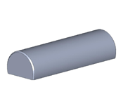
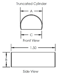
The truncated cylinder is the least expensive modified cylinder. It is used in close quarters where reduced profile height and or increased stability due to the flat base are important. These hardened and dimensionally stabilized stainless steel cylinders are precision ground and machine lapped to provide excellent cylindricity with close dimensional tolerance. The highly uniform low microinch surface texture generated by the machine lapping leads to low hysteresis and excellent repeatability. Two parallel mounted cylinders form a very high quality substitute for the hard-to-manufacture vee groove.The truncated cylinders are usually clamped or glued into position.
| Part No. | A-Diameter ±.0001" | B-Height ±.002" | C-Length Reference | D-Width Reference |
|---|---|---|---|---|
| 187-TC | .1875" 4.763 mm |
|||
| 250-TC | .250" 6.35 mm |
.167" 4.242 mm |
1.5" 38.100 mm |
.235" 5.97 mm |
| 312-TC | .3125" 7.9375 mm |
.208" 5.283 mm |
1.5" 38.100 mm |
.294" 7.468 mm |
| 375-TC | .3750" 9.525 mm |
.250" 6.35 mm |
1.5" 38.100 mm |
.353" 8.966 mm |
| 500-TC | .500" 12.700 mm |
.334" 8.484 mm |
1.5" 38.100 mm |
.471" 11.963 mm |
| 625-TC | .625" 15.875 mm |
1.5" 38.100 mm |
||
| 750-TC | .750" 19.05 mm |
.500" 12.700 mm |
1.5" 38.100 mm |
.707" 17.958 mm |
| 100-TC | 1.00" 25.4 mm |
.750" 19.05 mm |
1.5" 38.100 mm |
.866" 21.1 mm |
Truncated and Recessed Cylinder
Made from Hardened Stainless Steel with an Extended Glue Line
| Downloads | ||
|---|---|---|
| Solidworks | IGES | |
| N/A | ||
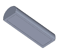
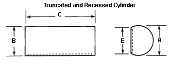
The truncated and recessed cylinder is used where reduced profile height and or increased mechanical stability provided by the flat rim are required. This design has a .005" deep recess on its flat surface that is made very rough by Electrical Discharge Machining. This rough surface is used in applications where the cylinder is glued in place. These hardened and dimensionally stabilized stainless steel cylinders are precision ground and machine lapped to provide excellent cylindricity with close dimensional tolerance. The highly uniform low microinch surface texture generated by the machine lapping leads to low hysteresis and excellent repeatability. Two parallel mounted cylinders form a very high quality substitute for the hard-to-manufacture vee groove. The truncated and recessed cylinder is usually clamped, glued, or clamped and glued into position.
| Part No. | A-Diameter ±.0001" | B-Height ±.002" | C-Length Reference | E-Width Reference |
|---|---|---|---|---|
| 187-TCR | .1875" 4.763 mm |
1.5" 38.100 mm |
||
| 250-TCR | .250" 6.35 mm |
.167" 4.242 mm |
1.5" 38.100 mm |
.235" 5.97 mm |
| 312-TCR | .3125" 7.9375 mm |
.208" 5.283 mm |
1.5" 38.100 mm |
.294" 7.468 mm |
| 375-TCR | .3750" 9.525 mm |
.250" 6.35 mm |
1.5" 38.100 mm |
.353" 8.966 mm |
| 500-TCR | .500" 12.700 mm |
.334" 8.484 mm |
1.5" 38.100 mm |
.471" 11.963 mm |
| 625-TCR | .625" 15.875 mm |
1.5" 38.100 mm |
||
| 750-TCR | .750" 19.05 mm |
.500" 12.700 mm |
1.5" 38.100 mm |
.707" 17.958 mm |
| 100-TCR | 1.00" 25.4 mm |
.750" 19.05 mm |
1.5" 38.100 mm |
.866" 21.1 mm |
Truncated and Recessed Cylinder Pricing
| Part # | Price | Purchase |
|---|---|---|
| 187-TCR | $16.78 | |
| 250-TCR | $16.78 | |
| 312-TCR | $17.27 | |
| 375-TCR | $18.10 | |
| 500-TCR | $19.36 | |
| 625-TCR | $25.19 | |
| 750-TCR | $31.57 | |
| 100-TCR | $35.86 | |
Truncated Cylinder with Blind Holes
Made from Hardened Stainless Steel at 58 HRC.

| Downloads | ||
|---|---|---|
| Solidworks | IGES | |
| N/A | ||
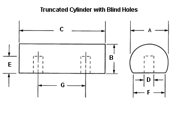
The truncated cylinder with blind holes is a low-cost modified cylinder with high mounting strength. This version is usually pinned and glued to hold it in position. This design is often employed in production applications where large numbers of kinematic components require maximum economy. These hardened and dimensionally stabilized stainless steel cylinders are precision ground and machine lapped to provide excellent cylindricity with close dimensional tolerance. The highly-regular low micro inch surface texture generated by the machine lapping leads to low hysteresis and excellent repeatability. Two parallel mounted cylinders form a very high quality substitute for the hard-to-manufacture vee groove. The reduced profile height, the added stability of the flat base, and the higher load-carrying capacity are all good selling points for this design.
Truncated Cylinder with Blind Holes Specifications
| Part No. | A-Diameter ±.0001" | B-Height ±.002" | C-Length Reference | D- Diameter | E-Depth | F-Width Reference | G-Center to Center |
|---|---|---|---|---|---|---|---|
| 187-TC-BH | .1875" 4.763 mm |
1.5" 38.100 mm |
1.00" 25.4 mm |
||||
| 250-TC-BH | 0.250" 6.35 mm |
0.167" 4.242 mm |
1.5" 38.100 mm |
0.0625" 1.59 mm |
0.0625" 1.59 mm |
0.235" 5.97 mm |
1.00" 25.4 mm |
| 312-TC-BH | 0.3125" 7.9375 mm |
0.208" 5.283 mm |
1.5" 38.100 mm |
0.09375" 2.38 mm |
0.09375" 2.38 mm |
0.294" 7.468 mm |
1.00" 25.4 mm |
| 375-TC-BH | 0.3750" 9.525 mm |
0.250" 6.35 mm |
1.5" 38.100 mm |
0.125" 3.18 mm |
0.125" 3.18 mm |
0.353" 8.966 mm |
1.00" 25.4 mm |
| 500-TC-BH | 0.500" 12.700 mm |
0.334" 8.484 mm |
1.5" 38.100 mm |
0.15625" 3.97 mm |
0.15625" 3.97 mm |
0.471" 11.963 mm |
1.00" 25.4 mm |
| 625-TC-BH | 0.625" 15.875 mm |
1.5" 38.100 mm |
|||||
| 750-TC-BH | .750" 19.05 mm |
.500" 12.70 mm |
1.5" 38.100 mm |
.707" 17.958 mm |
1.00" 25.4 mm |
||
| 100-TC-BH | 1.00" 25.4 mm |
.750" 19.05 mm |
1.5" 38.100 mm |
.866" 21.1 mm |
1.00" 25.4 mm |
Truncated Cylinder with Blind Holes Pricing
| Part # | Price | Purchase |
|---|---|---|
| 187-TC-BH | $21.18 | |
| 250-TC-BH | $21.18 | |
| 312-TC-BH | $22.22 | |
| 375-TC-BH | $23.60 | |
| 500-TC-BH | $25.96 | |
| 625-TC-BH | $31.52 | |
| 750-TC-BH | $37.07 | |
| 100-TC-BH | $44.00 | |
Truncated Cylinder with Counterbored Holes
Made from Hardened Stainless Steel with an Extended Glue Line


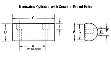
The truncated cylinder with counterbored holes is our second most popular cylindrical component. It is used when the components must be held in place from the front side. These hardened and dimensionally stabilized stainless steel cylinders are precision ground and machine lapped to provide excellent cylindricity with close dimensional tolerance. The highly uniform low microinch surface texture generated by the machine lapping leads to low hysteresis and excellent repeatability. The land left around the edge of the flat due to the recess forms an extremely stable mounting surface. Two parallel mounted cylinders form a very high quality substitute for the hard-to-manufacture vee groove.
| Downloads | ||
|---|---|---|
| Solidworks | IGES | |
| N/A | ||
This design has a 0.005" deep recess on its flat surface that is made very rough by Electrical Discharge Machining ( EDM ). When maximum reliability is required, glue may be applied to this rough surface to form a permanent bond between this component, the machine screw, and the mounting surface. This component is machined for use with a standard socket head cap screw.
The "H" dimension is from center line to center line. It is 1.00" (25.4 mm) on all parts.
| Part No. | A-Diameter ±.0001" | B-Height ±.002" | C-Length Reference | D-Dia Reference | E-Dia. Reference | F-Depth Reference | G-Width Reference | Screw Size |
|---|---|---|---|---|---|---|---|---|
| 250-TCR-CB | .250" 6.35 mm |
.167" 4.242 mm |
1.5" 38.100 mm |
.094" 2.288 mm |
.187" 4.750 mm |
.086" 2.184 mm |
.235" 5.97mm |
#2 |
| 312-TCR-CB | .3125" 7.9375 mm |
.208" 5.283 mm |
1.5" 38.100 mm |
.125" 3.175 mm |
.218" 5.537 mm |
.125" 3.175 mm |
.294" 7.468 mm |
#4 |
| 375-TCR-CB | .3750" 9.525 mm |
.250" 6.35 mm |
1.5" 38.100 mm |
.125" 3.175 mm |
.218" 5.537 mm |
.125" 3.175 mm |
.353" 8.966 mm |
#4 |
| 500-TCR-CB | .500" 12.700 mm |
.334" 8.484 mm |
1.5" 38.100 mm |
.154" 3.91 mm |
.281" 7.137 mm |
.138" 3.505 mm |
.471" 11.963 mm |
#6 |
| 625-TCR-CB | .625" 15.875 mm |
1.5" 38.100 mm |
||||||
| 750-TCR-CB | .750" 19.05 mm |
.500" 12.700 mm |
1.5" 38.100 mm |
.206" 5.323 mm |
.375" 9.52 mm |
1.90" 4.826 mm |
.707" 17.958 mm |
#10 |
| 100-TCR-CB | 1.00" 25.4 mm |
.750" 19.05 mm |
1.5" 38.100 mm |
.206" 6.35 mm |
.375" 9.52 mm |
0.250" 6.35 mm |
.866" 21.1 mm |
1/4" |
Truncated Cylinder with Counterbored Holes Pricing
| Part # | Price | Purchase |
|---|---|---|
| 250-TCR-CB | $41.69 | |
| 312-TCR-CB | $41.69 | |
| 375-TCR-CB | $42.35 | |
| 500-TCR-CB | $52.69 | |
| 625-TCR-CB | $53.24 | |
| 750-TCR-CB | $53.79 | |
| 100-TCR-CB | $69.96 | |
Truncated and Threaded Cylinder
Made from Hardened Stainless Steel with an Extended Glue Line and Tapped Holes
| Downloads | ||
|---|---|---|
| Solidworks | IGES | |
| N/A | ||
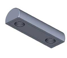
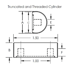
Because this cylinder is held from behind with machine screws, there is no interruption of the cylindrical The truncated and threaded cylinder is our most widely used cylindrical component. The land left around the edge of the flat due to the recess forms an extremely stable mounting surface. These hardened and dimensionally stabilized stainless steel cylinders are precision ground and machine lapped to provide excellent cylindricity with close dimensional tolerance.
The highly-regular low microinch surface texture generated by the machine lapping leads to low hysteresis and excellent repeatability. Two parallel mounted cylinders, held in place by machine screws, form a very high quality substitute for the hard to manufacture vee groove. This design has a .005" deep recess on its flat surface that is made very rough by Electrical Discharge Machining. When maximum reliability is required, glue may be applied to this rough surface to form a permanent bond between this component, the machine screw, and the mounting surface.
| Part No. | A-Diameter ±.0001" | B-Height ±.002" | C-Length Reference | E-Depth Reference | F-Center Line | H-Width Reference | Screw Size |
|---|---|---|---|---|---|---|---|
| 187-TCR-T | .1875" 4.763 mm |
1.5" 38.100 mm |
|||||
| 250-TCR-T | .250" 6.35 mm |
.167" 4.242 mm |
1.5" 38.100 mm |
.125" 3.175 mm |
1.00" 25.4 mm |
.235" 5.97 mm |
6-32 |
| 312-TCR-T | .3125" 7.9375 mm |
.208" 5.283 mm |
1.5" 38.100 mm |
.154" 3.91mm |
1.00" 25.4 mm |
.294" 7.468 mm |
6-32 |
| 375-TCR-T | .3750" 9.525 mm |
.250" 6.35mm |
1.5" 38.100mm |
.200" 5.08 mm |
1.00" 25.4 mm |
.353" 8.966mm |
10-32 |
| 500-TCR-T | .500" 12.700 mm |
.334" 8.484 mm |
1.5" 38.100 mm |
.250" 6.35 mm |
1.00" 25.4 mm |
.471" 11.963 mm |
1/4"-20 |
| 625-TCR-T | .625" 15.875 mm |
||||||
| 750-TCR-T | .750" 19.05 mm |
.500" 12.700 mm |
1.5" 38.100 mm |
.250" 6.35 mm |
1.00" 25.4 mm |
.707" 17.958 mm |
1/4"-20 |
| 100-TCR-T | 1.00" 25.4 mm |
.750" 19.05mm |
1.5" 38.100mm |
.250" 6.35mm |
1.00" 25.4mm |
.866" 21.1mm |
1/4"-20 |
Truncated and Threaded Cylinder Pricing
| Part # | Price | Purchase |
|---|---|---|
| 250-TCR-T | $40.37 | |
| 312-TCR-T | $40.37 | |
| 375-TCR-T | $41.20 | |
| 500-TCR-T | $43.12 | |
| 625-TCR-T | $44.25 | |
| 750-TCR-T | $45.38 | |
| 100-TCR-T | $47.96 | |
The Rose Bud Kinematic Coupling
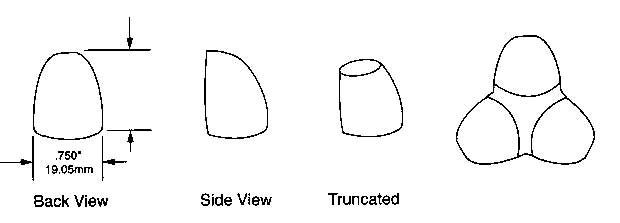
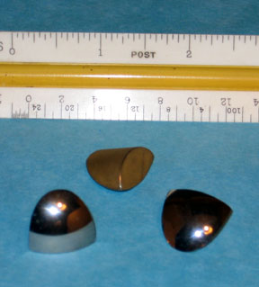
The Three Ball Kinematic Coupling ( Rosebud ) is one of the top performing location devices. It restricts three degrees of freedom, without the distortion caused by clamping forces. This three-ball device takes the place of the conical cup used in the classical kinematic system. However a three-ball system is limited to rather light load as the overall size of the coupling grows dramatically when larger balls must be used to cope with heavier pay loads.
The solution in high load situations is to use a Rose Bud configuration. By cutting cylindrical fingers out of the side of a large diameter ball, and then cutting this finger in half, a small super rigid component or rose petal is produced that is easy to mount on the Kinematic Platform. To rigidly mount these components, you simply machine a 120 degree "Y" shaped trench in the platform, with an end mill of a radius, that matches the cylindrical radius of the rose petal and glue the individual components in. Because the resulting force on the components is down and out and they are buried in the "Y" shaped trench, the limiting load factor is the strength of the material that the Kinematic Platform is made of. The spherical surfaces of these components retain the high quality geometry and excellent surface finish of the precision balls that they were removed from. To reduce the overall height of the assembly, the tops of the cylindrical fingers are usually cut down some.
These devices can be prepared for surface mounting by drilling and threading a hole in the base plane. When this is done, much of the system's rigidity is lost. A single standard component has been developed that will fill most kinematic applications. A three eighths of an inch ( 3/8", 9.53 mm) radius, that is three three quarters of an inch ( 3/4", 19 mm) diameter cylinder is cut out of a one and one quarter inch ( 1 1/4", 31.75 mm) diameter sphere. This cylindrical finger is then cut in half. The nest provided by three of these components is compatible with any ball size from three eighths of an inch ( 3/8", 9.53 mm ) to over one inch ( 25.4 mm ) diameter. The material usually used for manufacturing these components is tungsten carbide. This is the stiffest, hardest commercially available material with a Young's Modulus of Elasticity of 98,000,000 P.S.I. and a hardness of 91 HRA. They are also available in a micro grained stainless steel that is hardened to 58 HRC minimum. Other combinations of radii and material will be produced to fill any specific customer needs. These include corrosion resistance and special magnetic or electrical properties.
Rose Bud Pricing
| Part # | Description | Price | Purchase |
|---|---|---|---|
| 375-RB | ROSE BUD, 0.375" ( 3/8" ), STAINLESS STEEL | $59.40 | |
| 375-TRB | ROSE BUD, 0.375" ( 3/8" ), TRUNCATED, STAINLESS STEEL | $59.40 | |
Around The Corner
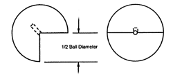
Around the corner is a rather unique kinematic component that allows for wide-angle positioning of the portable platform. Using these kinematic devices, the platform can literally go to any angle from less than horizontal to more than vertical.
These components are available in a micro grain stainless steel that has a minimum hardness of 58 HRC or in tungsten carbide, which is the stiffest, hardest commercially available material. Tungsten carbide has a Young's modulus of elasticity of 98,000,000 P.S.I. and a hardness of 91 HRA.
An optional design for this component is to thread the pinhole, but it is usually very awkward to machine the intricate details to bring a cap screw through the platform at a 45 degree angle. In addition, Electrical Discharge Machining ( EDM ) the thread in these hard materials adds a considerable cost to such components.
Around the Corner Pricing, Steel
Around the Corner Pricing, Tungsten Carbide
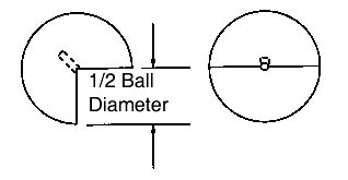
These devices are produced by cutting a 90 degree notch out of a very precise complete ball. A hole is then drilled in the center of the line formed by the triangular gable. A pin glued into this hole is used to reinforce its connection to the edge of the kinematic platform. These components are usually glued onto the Kinematic Platform with high shear strength epoxy glue.
Around the Corner
| Part # T.C. | Part # Stainless | Sphere Diameter | Pin Diameter |
|---|---|---|---|
| 500AC | 500AC | .50" | .062" |
| TC | 12.7 mm | 1.59 mm | |
| 750AC | 750AC | .75" | .125" |
| TC | 19.05 mm | 3.175 mm | |
| 100AC | 100AC | 1.00" | .125" |
| TC | 25.4 mm | 3.175 mm |
Around the comer is a rather unique kinematic component that allows for wide-angle positioning of the portable platform. Using these kinematic devices the platform can literally go to any angle from less than horizontal to more than vertical. These devices are produced by cutting a 90 degree notch out of a very precise complete ball. A hole is then drilled in the center of the line formed by the triangular gable. A pin glued into this hole is used to reinforce its connection to the edge of the kinematic platform. These components are usually glued onto the Kinematic Platform with high shear strength epoxy glue.
These components are available in a micro grain stainless steel that has a minimum hardness of 58 HRC or in tungsten carbide, which is the stiffest, hardest commercially available material. Tungsten carbide has a Young's modulus of elasticity of 98,000,000 P.S.I, and a hardness of 91 HRA. An optional design for this component is to thread the pinhole, but it is usually very awkward to machine the intricate details to bring a cap screw through the platform at a 45 degree angle. In addition Electrical Discharge Machining the thread in these hard materials adds a considerable cost to such components.
Flat Prismatic Components for Kinematics

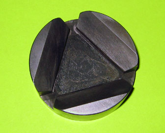
In kinematic applications, plane flat surfaces have a higher load carrying capacity than cylindrical or spherical ones. Plate surfaces with very fine surface texture are quite slippery, so they provide excellent alignment of the mating spheres. Producing high quality flat planes on prismatic devices requires a unique approach. Lapping the inside flat faces of a Vee Block, or even worse, the inside faces of a Trihedral Cup is not a practical task. These devices are also known as: Kelvin Clamps, Tetrahedron, Tetrahedral, Trihedral, Trihedron. An approach that can produce the highest quality internal prismatic devices is the split design. Instead of constructing the device as a monolith, which is conventional wisdom, each facet of the prism is produced as a separate but symmetrical unit. A very high quality flat facet can be easily produced on the truncated surface of a cylindrical post. Rigidity is not lost by splitting the faces of the prism because the cylindrical design provides a simple method for extremely rigid mounting. By machining a trench in the Kinematic Platform, with an end mill, that has the same radius as the cylindrical post itself and gluing the assembly together under load, an extremely rigid assembly results. The reason that this design can so far outstrip the rigidity of a monolithic component is not so obvious, but it is due to the inherent weakness in the joint connecting the monolith to the Kinematic Platform.
For light loads there is seldom any reason to use this more complicated flat facet design, when three spheres will form an excellent trihedral cup and two cylinders a fine Vee Block. A universal component that will fill a broad array of high load kinematic applications is a three quarter inch ( 3/4", 0.75", 19.05 mm ) diameter cylindrical post that is truncated at a 45 degree angle. This one component will function well with any ball size from one half inch ( 1/2", 0.5", 12.7 mm ) to over one inch ( 1", 25.4 mm ). Better repeatability can be achieved by using a steeper angle but this will reduce the load carrying capacity. These components can be produced for surface mounting by drilling and threading a hole in the flat base but in doing so much of the system's rigidity is lost. Because the relative cost of raw material is rather small in relation to the overall cost of this component, tungsten carbide with its tremendous stiffness or Young's Modulus of Elasticity of 98,000,000 P.S.I, and high hardness of 91-HRA has been chosen as the standard material. There is wide latitude of design options of both size and materials to cope with different loads, corrosive environments, temperature, as well as magnetic and electrical qualities. We will custom build just about any design to fill specific customer needs.
A typical steel prismatic component costs $45.00.
| Downloads | ||
|---|---|---|
| Solidworks | IGES | |
Plain Flat Kinematic Component
For many years past the trend in kinematic coupling designs has shunned the classical Conical Cup, Vee Block and flat plane as described by both Maxwell and Lord Kelvin in separate publications in the late eighteen hundreds. This reluctance was based on the great difficulty of generating very high quality Conical and Vee Block surfaces. Standardized kinematic components are now available that solve these age old quality limitations. Availability of these components has rekindled interest in the classical designs with the many advantages that are offered by the diverse components. An outstanding example of these advantages is the ability of an axis to pivot with unheard of accuracy along the line axis between the Conical Cup and the Vee Block.
Among the kinematic purists out there, this will end up as a button pushing opportunity. If the Vee Block is pointed at the bisector of the kinematic axis of the coupling, the line axis of the pivot could undulate because the two tangent contacts are not on the pivot axis. If on the other hand, the Vee Block is pointed parallel to the axis, we want to depict that we are no longer in strict compliance with kinematic principles. If there is one thing that we have learned through the years, is that kinematics in general are very forgiving. A line of standardized flat components are available to go along with the conical cups and the more sophisticated components like the Rose Bud and Prismatic Components. The design of the first of the standard flat devices is for everyday applications. It is a disk made of micro "rained" stainless steel that is hardened to 58 HRC minimum. These disks are ground parallel and the working surface is lapped flat with a 2 microinch (.05 micrometer) Ra surface quality. There is a blind threaded hole in the back surface to hold them on the Kinematic Platform.
Standard Flat Components
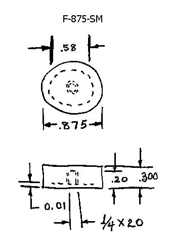
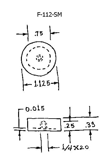
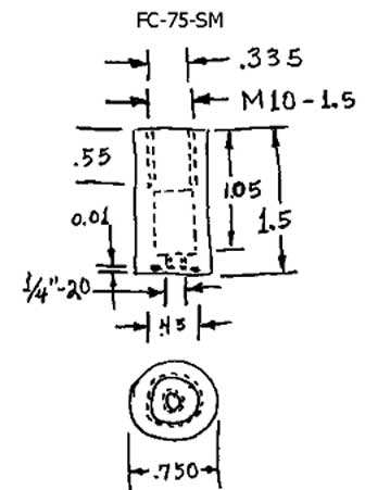
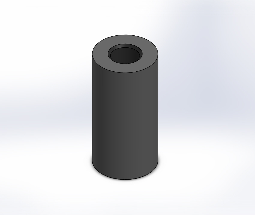
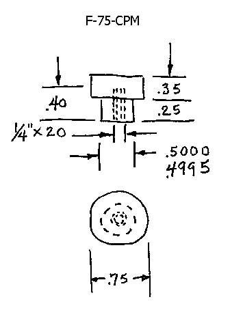
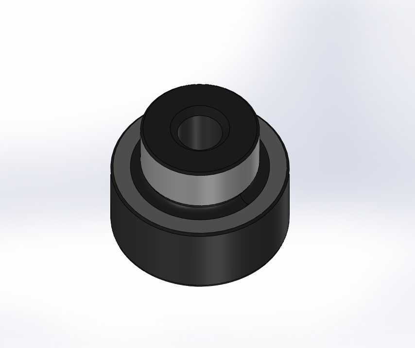
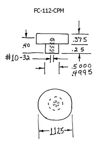
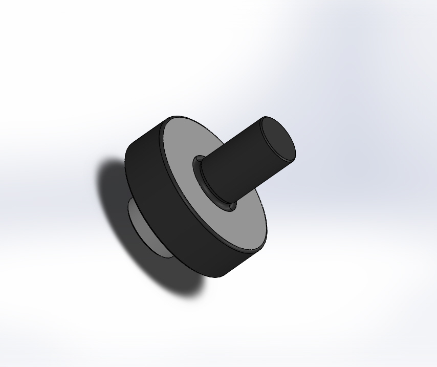
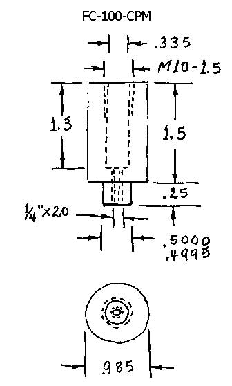
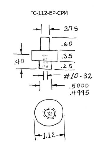
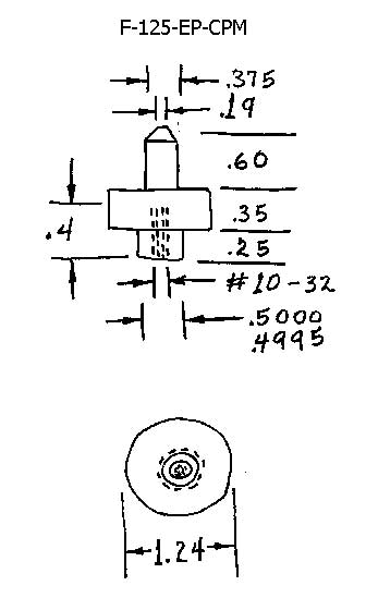
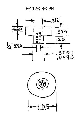
Standard Flat Components - Key to Sketches
| Sketch No. | Part No. | Description |
|---|---|---|
| 1. | F-875-SM | Flat - Surface Mounted |
| 2. | F-112-SM | Flat - Surface Mounted |
| 3. | FC-750-SM | Flat Cylinder - Surface Mounted |
| 4. | F-750-CPM | Flat - Cylindrical Post Mounted |
| 5. | F-112-CPM | Flat - Cylindrical Post Mounted |
| 6. | FC-100-CPM | Flat Cylinder - Cylindrical Post Mounted |
| 7. | F-112-EP-CPM | Flat with Extension Post - Cylindrical Post Mounted |
| 8. | F-125-EP-CPM | Flat with Extended Post - Cylindrical Post Mounted |
| 9. | F-112-CB-CPM | Flat - Cylindrical Post Mounted with Counterbore |
Standard Flat Components - Pricing
Special Order Only
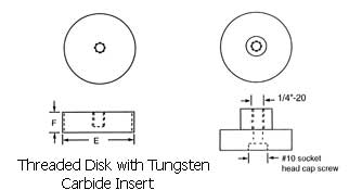
We will custom manufacturer any special design required to fill specific customer needs for corrosion resistance and magnetic or electrical properties. The third option has the same design features as the standard flat devices except it has a precision ground cylindrical boss that provides excellent locate-ability. For premium applications, there is a steel disk that is threaded on the outside diameter. There is a smaller tungsten carbide disk glued in the center of the working face. This carbide disk is lapped flat with 1 microinch (.025 micrometer) Ra surface quality. Tungsten Carbide is the stiffest, hardest, commercially available material, with a Young's Modulus of Elasticity of 98,000,000 PSI and a hardness of 91 HRA. This thread on the disk can be used as an adjustment or to lock the device in place. As an alternative, it can simply be permanently glued into an oversize counterbore. There are four holes drilled in the top face. This allows adjustment up and down by rotating it with a special Spanner Wrench, Part Number SW -1.
The Kinematic Quarter Round
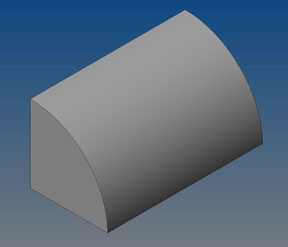
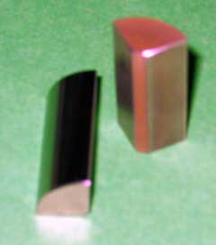
The Quarter Round is a different approach in kinematic design. A different reality is unlocked by simply thinking in different terms. How do you describe the surface of a Kinematic Platform?
| Downloads | ||
|---|---|---|
| Solidworks | IGES | |
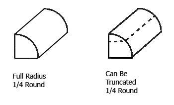
Is it the top of the physical plate or could it be better defined as the central plane of the kinematic system? What this changes is the very nature of the kinematic system. In order to achieve very high levels of mechanical perfection i.e. geometry and surface texture in the kinematic elements, they are produced as separate entities that are then attached to the platform. In order to get enhanced physical properties, i.e. hardness, stiffness and corrosive resistance in kinematic elements that are better than the material of the platform itself, the same approach is used. By simply burying these enhanced kinematic elements in self supporting trenches that are machined into platform proper, the rigidity and the resonate frequency of the platform can be
The Quarter Round
A high quality Vee Block is one of the most difficult pieces of kinematic hardware to produce. For this reason, two parallel cylinders have become a popular Ultimate Round for the flat angled facets of a Vee Block. Although very high quality cylinders are easy to produce, it is difficult to rigidly attach them to the Kinematic Platform. Cylinders of large diameter have a high profile, are heavy, and quite expensive By splitting a precision lapped cylinder of rather large diameter into quarters, we produce components that can be rigidly glued into a simple slot or trench machined into the Kinematic Platform.
The Ultimate Quarter Round
The "Ultimate Quarter Round" is the zenith of perfection in kinematic components. When used in combination with grade 2.5 quality tungsten carbide spheres, these components will challenge present capability of error evaluation. When used in a well-designed kinematic system, the error budget will be measured in nanometers and microradians. How is this extraordinary performance achieved? We start with the choice of materials. The stiffness of tungsten carbide, measured in compression, is on the order of one hundred and twelve million pounds per square inch. This is only surpassed by diamond in readily available materials. The hardness of tungsten carbide is 91 HRA or 1500 Vickers.
Abrasion tests rate it at 20 to 30 times hard steel. Now we compound these qualities by producing the material with a particulate grain diameter that is less than one micron. As if this isn't enough, the material hot isostatic pressed to achieve 100% density, virtually eliminating any porosity. The original cylinders that are used to produce the "Ultimate Quarter Round" are first centerless ground using a diamond wheel. They are then ring lapped to correct any Polylobular condition. Next they are machine lapped with three progressively finer diamond compounds, to achieve a surface quality that is below 0.1 microinches Ra, 2.5 nanometers. The normal mounting technique is to glue the component quarter rounds into a machined trench with a high strength ceramic filled epoxy. If the epoxy glue is objectionable, for vacuum or other reasons, a threaded hole can be provided at the apex of the triangular back mounting surfaces. This mounting method has been well proven in high-end optical applications. Unique Quarter Round components will be custom manufactured to meet any customer requirement. These may include corrosion resistance and special magnetic or electrical properties.
| Part Number | Material | Original Cylindrical Diameter | Length |
|---|---|---|---|
QR-750-S |
Quarter Round Steel |
.750" (19.05 mm) | 1.00" ( 25.4 mm) |
QR-750-TC |
Ultimate Round Tungsten Carbide |
.750" (19.05 mm) | 1.00" (25.4 mm) |
QR-100-S |
Quarter Round Steel |
1.00" (25.4 mm) | 1.00" (25.4 mm) |
QR-100-TC |
Ultimate Round Tungsten Carbide |
1.00" (25.4 mm) | 1.00" (25.4 mm) |
